
Organic positive temperature coefficient thermistor and manufacturing method therefor

Inactive Publication Date: 2005-02-03
TDK CORPARATION
View PDF16 Cites 11 Cited by
  • Summary
  • Abstract
  • Description
  • Claims
  • Application Information

AI Technical Summary

Benefits of technology

Thus, with the foregoing in view it is an object of the present invention to provide a P-PTC thermistor with excellent stability of resistance.
In the method for measuring oxygen content of the present invention, a sample containing an organic compound is impulse heated and melted and the oxygen contained in the sample is converted to carbon monoxide or carbon dioxide gas, after which the carbon monoxide or carbon dioxide gas is analyzed by infrared absorption spectrometry in order to measure the oxygen content of the aforementioned sample. In this way it is possible to measure not only the oxygen originally present in the chemical structure of the organic compound, but also oxygen which has contaminated the structure of the organic compound. Moreover, it is also possible to measure the total content of oxygen contained in a mixture of an inorganic compound and an organic compound. Consequently the oxygen content of the thermistor element provided in the P-PTC thermistor of the present invention can also be measured. In addition, the oxygen from the atmosphere, to which the components of the thermistor element are exposed, can be removed while the results of the measurements are consulted. In this way, the P-PTC thermistor of the present invention can be obtained efficiently.

Problems solved by technology

However, after a close study of conventional P-PTC thermistors, the inventors discovered that such conventional P-PTC thermistors lack stability of resistance.
That is, it was found that when such a P-PTC thermistor is operated and then returned to a non-operating state, its resistance is different from the resistance before operation (in most cases, higher than the resistance before operation), and that its resistance becomes unstable if it is stored for example for a long period of time.

Method used


Image

  • Organic positive temperature coefficient thermistor and manufacturing method therefor
  • Organic positive temperature coefficient thermistor and manufacturing method therefor
  • Organic positive temperature coefficient thermistor and manufacturing method therefor

Examples


example 1

57% by volume of straight chain low density polyethylene manufactured using a metallocene catalyst as the polymer matrix (Evolu2520, Mitsui Chemical, tradename), 35% by volume of filamentous particles made of nickel as the conductive particles (Type 210, INCO, trade name) and 8% by volume of polyethylene wax as the low molecular weight organic compound (PW655, Baker Petrolite, trade name) were placed in a Laboplast mill (Toyo Seiki, trade name). The mill had a chamber capacity of 60 cm3, while the total volume of the materials used was 45 cm3 when converted to true density.

Next, the interior of the kneading chamber of the mill was decompressed to about 6.7 kPa (about 50 Torr) using a vacuum / purge unit (Toyo Seiki), after which the chamber was sealed.

Next, heating and kneading was performed for 60 minutes at a temperature of 150° C. to obtain a kneaded product.

After completion of kneading, the resulting kneaded product was sandwiched between nickel foils (electrodes) having a ...

example 2

A P-PTC thermistor was prepared as in Example 1 except that instead of the kneading chamber of the mill being sealed after being decompressed to about 6.7 kPa (about 50 Torr) using a vacuum / purge unit, the kneading chamber of the mill was first decompressed to about 6.7 kPa (about 50 Torr) using a vacuum / purge unit, and then nitrogen was introduced until the pressure inside the chamber reached atmospheric pressure and the chamber was sealed. The results for oxygen content of the thermistor element and resistances are shown in Table 1.

example 3

A P-PTC thermistor was prepared as in Example 1 except that instead of the kneading chamber of the mill being sealed after being decompressed to about 6.7 kPa (about 50 Torr) using a vacuum / purge unit, the kneading chamber of the mill was first decompressed to about 6.7 kPa (about 50 Torr) using a vacuum / purge unit, and then argon gas was introduced until the pressure inside the chamber reached atmospheric pressure and the chamber was sealed. The results for oxygen content of the thermistor element and resistances are shown in Table 1.


PUM


Abstract

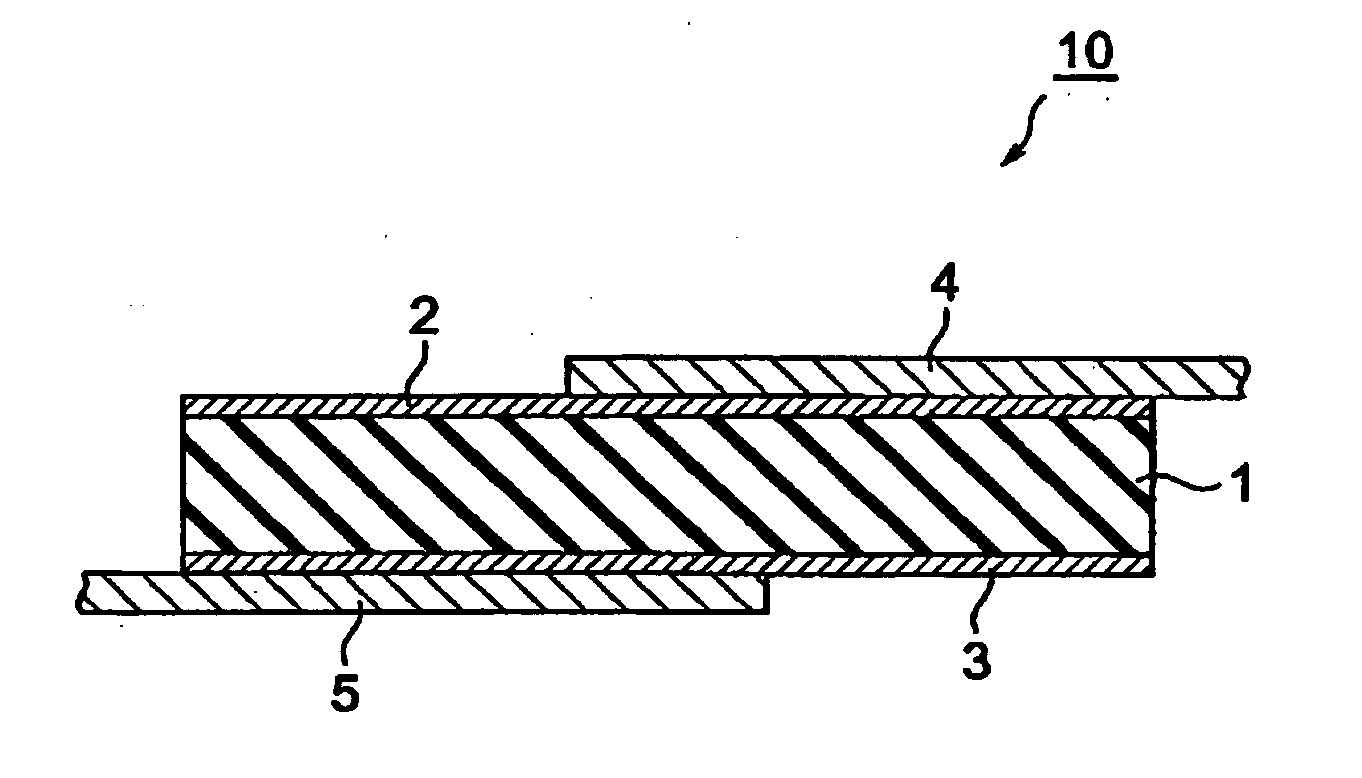
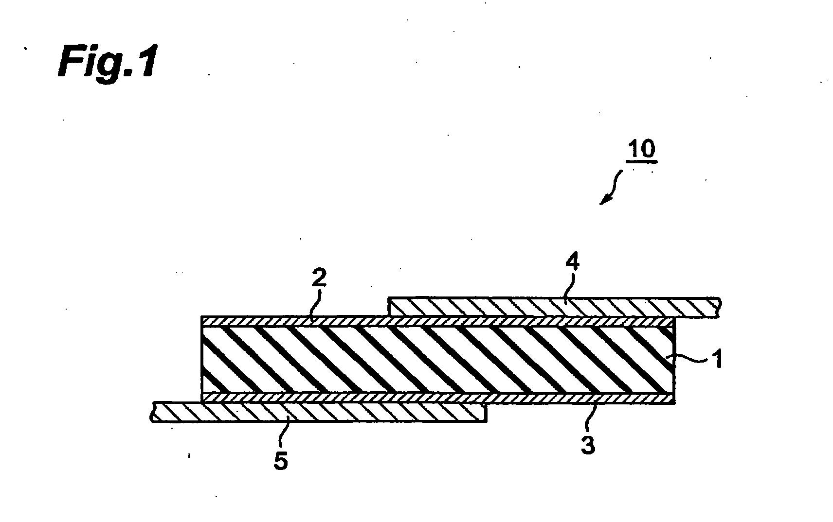
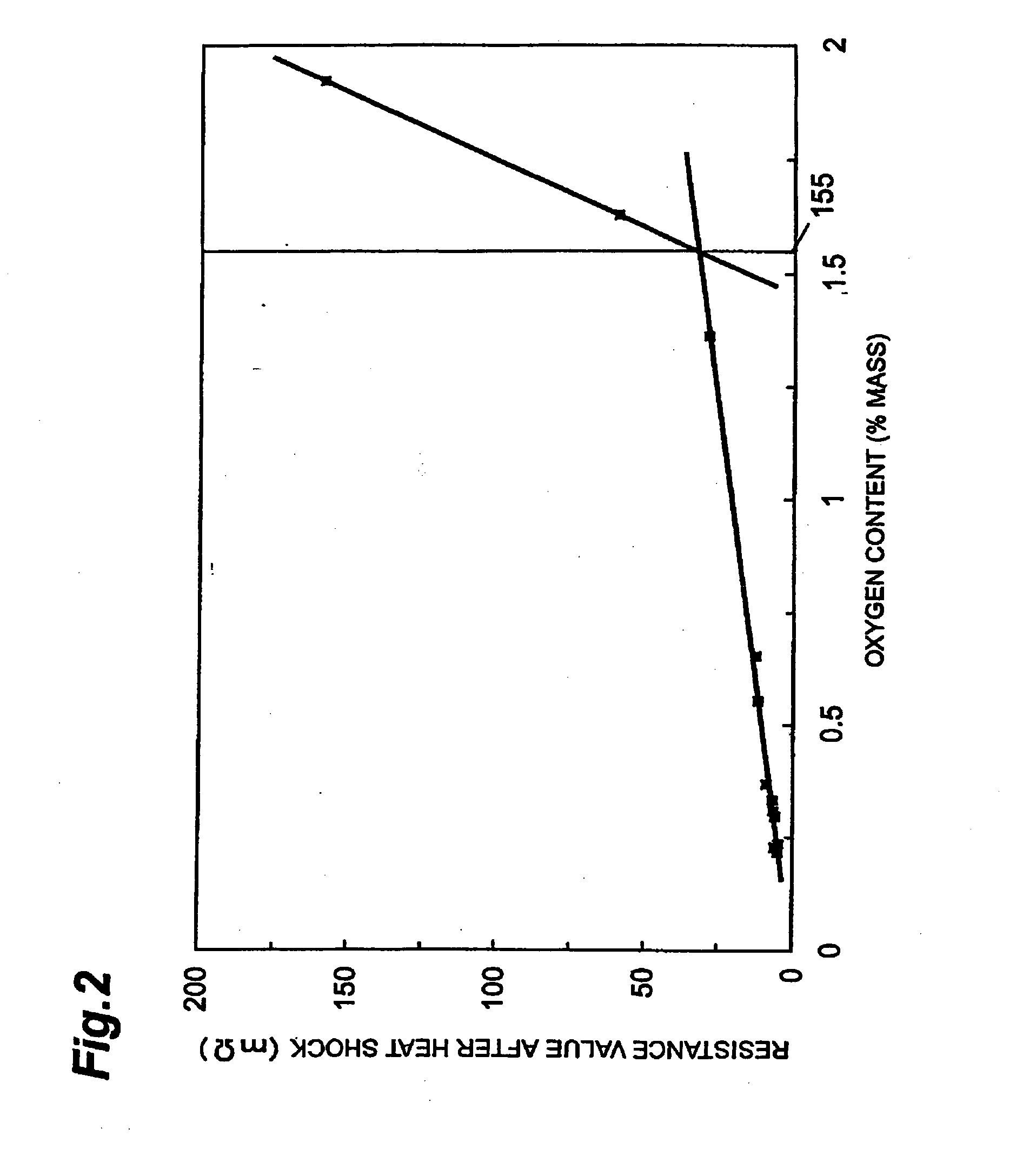
An organic positive temperature coefficient thermistor 10 having at least a pair of electrodes 2 and 3 positioned facing each other and a thermistor element 1 having a positive temperature coefficient of resistance which is positioned between the pair of electrodes 2 and 3, wherein the thermistor element 1 is a molded element consisting of a mixture which contains a polymer matrix and conductive particles having electronic conductivity, and wherein the thermistor element 1 has an amount of oxygen calculated by subtracting the amount of oxygen originally present in the various components of the mixture from the amount of oxygen contained in the thermistor element, which is 1.55 weight percent or less of the mass of the thermistor element.

Description

BACKGROUND OF THE INVENTION 1. Field of the Invention The present invention relates to an organic positive temperature coefficient thermistor and a manufacturing method therefor. 2. Related Background Art A positive temperature coefficient (PTC) thermistor has a composition which comprises at minimum a pair of electrodes positioned facing each other and a thermistor element positioned between this pair of electrodes. Moreover, this thermistor element has a “positive temperature coefficient of resistance,” meaning that within a specific temperature range, its resistance rises sharply as the temperature rises. Taking advantage of these features, positive temperature coefficient thermistors (hereunder “PTC thermistors”) are used for example as self-regulating heat generators, temperature sensors, current limiting elements, over-current protection elements and the like. For purposes of use as an over-current protection element in particular, a PTC thermistor needs to have low room-...

Claims


Application Information

Patent Timeline
IPC IPC(8): H01C7/02H01C17/00H01C17/065
CPCH01C17/065H01C7/027H01C7/02H01C17/00
Inventor HANDA, TOKUHIKO
Owner TDK CORPARATION
Learn More