Portable radio apparatus

a radio apparatus and portable technology, applied in the direction of electrical equipment, antenna details, antennas, etc., can solve the problems of narrow antenna bandwidth, inability to secure a sufficient band, and inability of radio devices of the prior art to enlarge the antenna bandwidth, etc., to achieve the effect of simple configuration

Inactive Publication Date: 2005-02-03
LENOVO INNOVATIONS LTD HONG KONG
View PDF12 Cites 14 Cited by
  • Summary
  • Abstract
  • Description
  • Claims
  • Application Information

AI Technical Summary

Benefits of technology

In accordance with the present invention, there is provided a portable radio apparatus capable of providing an impedance match by

Problems solved by technology

Therefore, regardless of whether the PDC or GSM system is adopted, the existing portable telephone having an antenna bandwidth of about a little under 6% cannot secure a sufficient band.
As just described, when the duplex function is added to the conventional portable radio apparatus, there arises a problem of the narrow bandwidth of the antenna.
The portable radio device of the prior art cannot enlarge the antenna bandwidth because the matching circuit thereof can only match with the antenna in a narrow frequency band.
When the duplex transmission circuit 5 is used in the TDMA communication, the matched state becomes worse on the human head side and hence the antenna characteristic is also deteriorated.
This leads to a problem that the circuit configuration becomes complex and the number of parts increases.
In association with the increase in the circuit size and complexity of the circuit, the l

Method used


Image

  • Portable radio apparatus
  • Portable radio apparatus
  • Portable radio apparatus

Examples


first embodiment

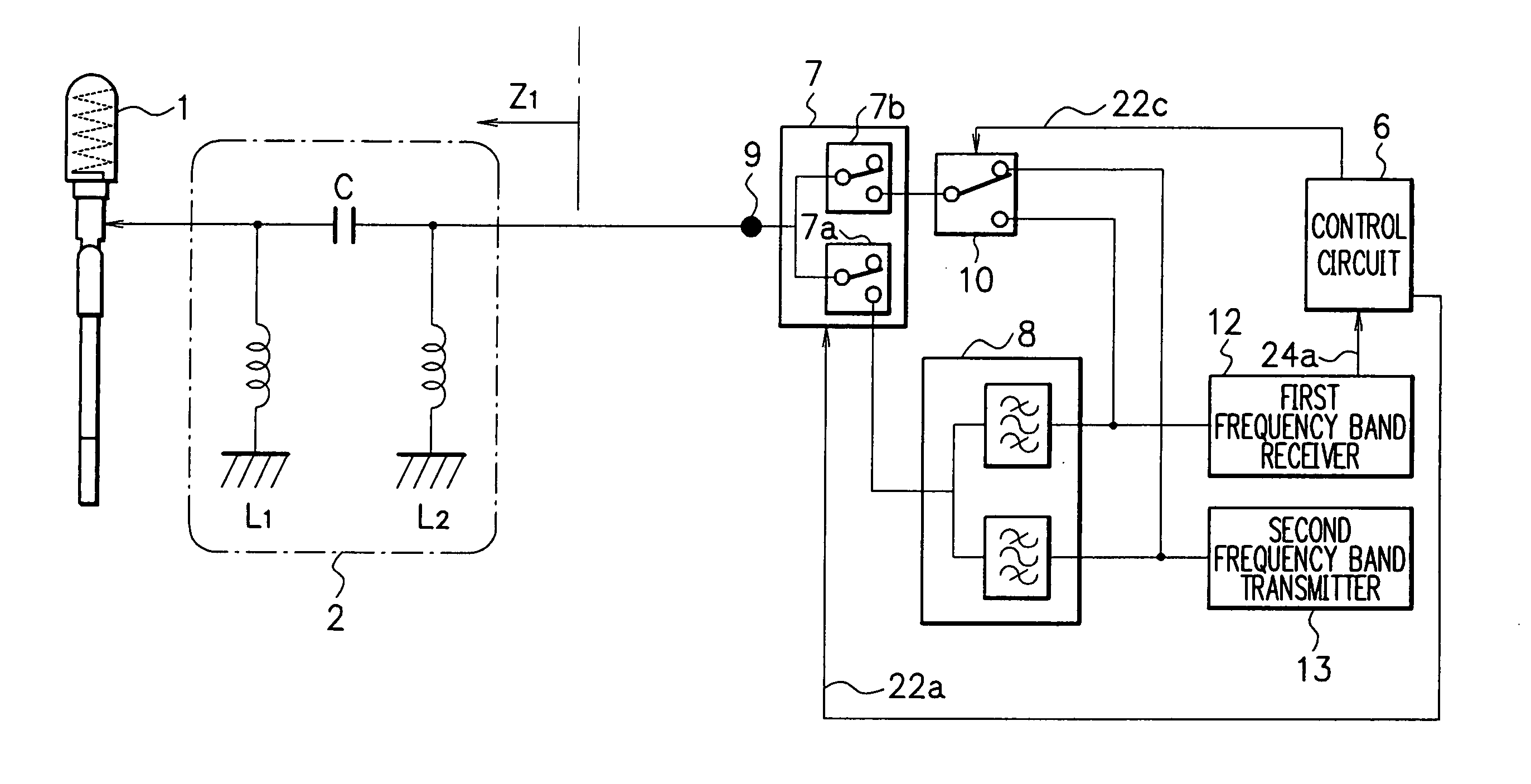
Description will now be given of a first embodiment in accordance with the present invention. FIG. 8 shows a configuration of a portable radio apparatus in the first embodiment. The apparatus includes a whip antenna 1, a matching circuit 2, a control circuit 6, a radio circuit changing switch 7, a unit for transmission and reception 8, a first frequency band transmission and reception changing switch 10, a first frequency band receiver circuit 12, and a first frequency band transmitter circuit 13.

The whip antenna 1 is an expandable and contractible antenna and includes a helical antenna in an end section thereof. The antenna 1 includes an expanding and contracting element adjusted to have a length of about λ / 4. Since the helical antenna is also adjusted to a length of about λ / 4, the element and the helical antenna are substantially equal in impedance to each other in the expanded and contracted or housed states. Therefore, the expansion and contraction of the whip antenna 1 will ...

second embodiment

The present invention is applicable also to the dual-band portable radio apparatus having the problem mentioned previously.

Description will now be given of a second embodiment of the present invention, in which the present invention is applied to a dual-band apparatus operating in a plurality of frequency bands.

FIG. 14 shows a configuration of a radio communication apparatus in the second embodiment. The apparatus includes, in addition to the components of the first embodiment, an expansion detecting switch 25, a matching circuit changing switch 18, an expansion matching circuit 21, a second frequency band receiver circuit 14, a second frequency band transmitter circuit 15, and a second frequency band transmission and reception change-over switch 11.

The expansion detecting switch 25 is a switch to detect an event in which the whip antenna 1 is in an expanded state. In the state in which the antenna 1 is expanded, the switch 25 feeds an expansion detection signal 26 to the cont...


PUM


Abstract

A portable radio apparatus capable of providing an impedance match with an antenna and a simple matching circuit for all frequency components of a frequency band to be used. A portable radio apparatus includes a whip antenna, a matching circuit, a radio section changing switch, a first frequency band receiver, and a first frequency band transmitter. A parallel inductor causing a resonance with a frequency lower than a resonance frequency of the antenna is connected in parallel to the antenna for a two-resonance characteristic to thereby conduct a wide-band operation.

Description

BACKGROUND OF THE INVENTION The present invention relates to a portable radio apparatus, and in particular, to a portable radio apparatus capable of providing an impedance match by use of an antenna and a matching circuit having a simple configuration for all frequency components in a frequency band to be used. Description of the Prior Art In a personal digital cellular (PDC) system as a Japanese standard system and in a global system for mobile communications (GSM) as a standard system in Europe, time division multiple access (TDMA), in which each station sends or receives signals only using a particular time slot allocated thereto, is employed to improve efficiency of frequency utilization. In the PDC system, different frequency bands are assigned respectively to an up communication and a down communication to thereby multiplex communications. A frequency band ranging from 810 MHz to 885 MHz is allocated to the down communication, and a frequency band ranging from 885 MHz to 9...

Claims


Application Information

Patent Timeline
IPC IPC(8): H01Q1/24H03H7/38H03H7/46H04B1/3822H04B1/40
CPCH01Q1/244H03H7/38H04B1/406H04B1/005H04B1/006H03H7/46
Inventor SAITO, TETSUYA
Owner LENOVO INNOVATIONS LTD HONG KONG
Why Eureka
Try Eureka