
Texturing systems for use in three-dimensional imaging systems

a technology of three-dimensional imaging and texture, applied in the direction of image data processing, cathode-ray tube indicators, filling the planer surface with attributes, etc., can solve the problems of limiting performance, accessing stored databases, and increasing processing power for animated 3d images for games and computer aided design applications

Inactive Publication Date: 2005-02-03
IMAGINATION TECH LTD
View PDF12 Cites 26 Cited by
  • Summary
  • Abstract
  • Description
  • Claims
  • Application Information

AI Technical Summary

Benefits of technology

Preferred embodiments of the invention are described below with reference to the drawings. In these embodiments the efficiency of trilinear texture filtering is improved by the generation of the lower-level texture mip-map on the fly from the upper-level mip-map, and with the use of texture caching and texture decompression as a means of meeting the high memory bandwidth requirements. Removing the need to read the lower-level mip-map in a separate memory access, removes page break problems and enhances performance.
Some data compression schemes lend themselves well to the generation of lower mip-maps on the fly by providing the required quantity of decompressed data and by closely supporting the filtering algorithm used to generate the lower-level mip-map. These techniques may be used to enhance the performance and quality of a 3D rendered image while minimising the hardware overhead.

Problems solved by technology

Three-dimensional image generation is computationally intensive.
Animated 3D images for games and Computer Aided Design (CAD) applications are becoming increasingly expensive in terms of processing power, as scenes become more photo-real and images are required to respond in real-time.
Accesses to stored databases are also a limiting factor to performance.
Texture mapping is particularly memory intensive especially when performing a filtering (that is, interpolation) operation where many texture pixels are read for every pixel that is mapped onto the display.
SDRAM has a higher access bandwidth capability than DRAM due to its pipelined architecture but is more expensive.
Semiconductor memory is very expensive and makes up a large percentage of the overall cost of a computer system.
The bandwidth requirement of a memory system is often directly related to the cost of that system.
In a fixed bandwidth system an increased bandwidth requirement can lead to a reduction of overall system performance.
Texturing is the most performance-intensive process of 3D imaging as it requires all textures to be retrieved from memory.
3] is used to improve the quality of the resulting image but there remain many artefacts that bilinear filtering cannot solve, including depth aliasing.
4], but there is still a problem called mip-banding.
Added to page change between mip-maps, this often achieves less than adequate 3D performance.
Unfortunately this is not always the case and very often the texture data resides in two or four separate words.
Equation 1 thus shows that, even with the use of texture caches, the physical memory bandwidth requirement still remains beyond the scope of any viable memory system.
But each has its associated problems: VQ and Palletised require two memory reads or large internal data caches and quality can be limited; DCT requires a large amount of decompression logic, and with a limited silicon budget this can be unfeasible; and many proprietary techniques provide limited compression ratios and quality.
For trilinear filtering, page breaks can be particularly problematic, where a number of mip-maps can often span more than one memory page.
As well as requiring a large memory bandwidth, a trilinear filtering operation can only be implemented in a large amount of logic and therefore silicon area.
Even using all available techniques for meeting the requirements, the constraints are still very difficult to meet if high quality real-time imaging is to be achieved.

Method used


Image

  • Texturing systems for use in three-dimensional imaging systems
  • Texturing systems for use in three-dimensional imaging systems
  • Texturing systems for use in three-dimensional imaging systems

Examples


Embodiment Construction

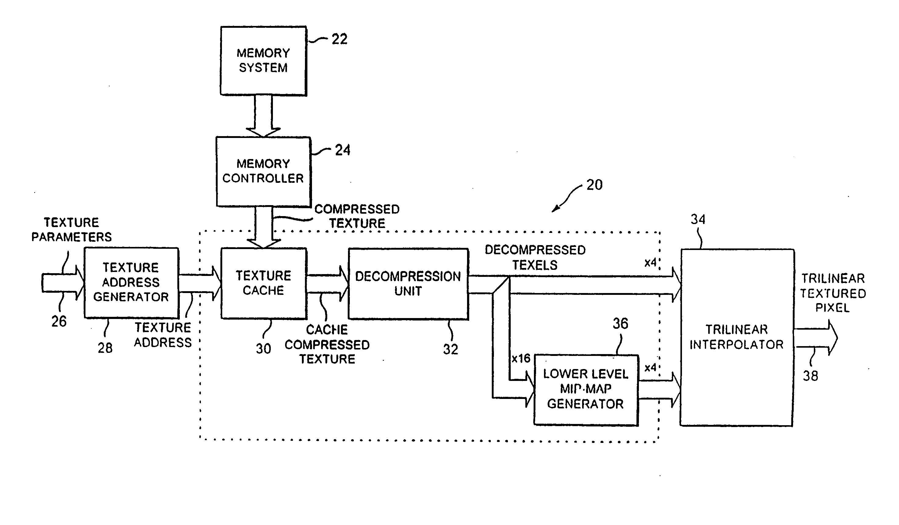
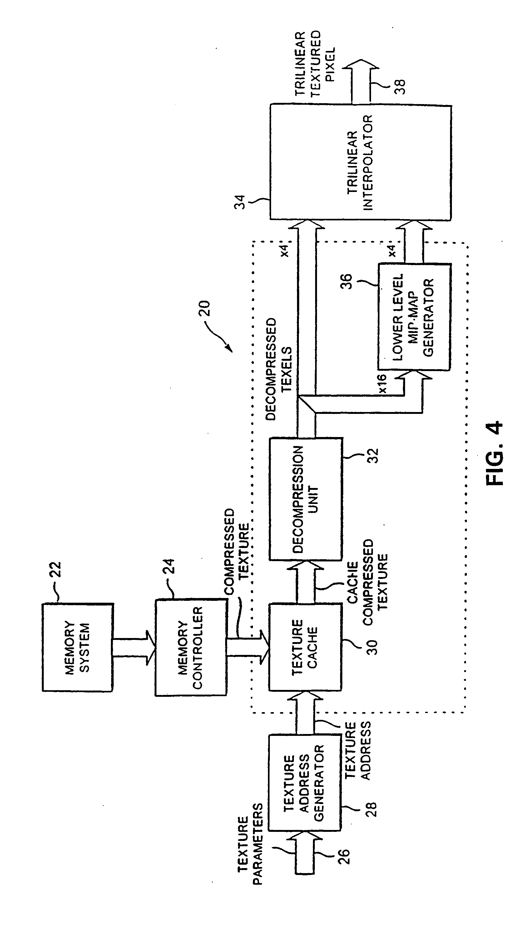
FIG. 4 shows a specific embodiment of a texturing system in accordance with the invention. The texturing system 20 comprises a memory system 22 forming part of the memory used by the imaging system as a whole, and which is controlled in known manner by a memory controller 24. The memory 22 holds inter alia a compressed texture map, and the output of the memory through the memory controller 24 consists of compressed texture from the requested part of the texture map. Parameters defining the texture required for any surface are received at an input 26 and applied to a texture address generator 28 to address the part of the memory 22 where the desired texture is located. The compressed texture is retrieved from memory by the memory controller 24 and held in a texture cache 30. The retrieved texture will correspond to a particular texture type representing the type of surface to be displayed. For example this may be part of a brick wall or the surface of a road. This surface texture wil...


PUM


Abstract

A texturing system for use in a three-dimensional imaging system comprises a memory (22) for storing mip-map data for use in texturing an image. A controller (24) retrieves from the memory the mip-map data required and this data is stored in a cache (30). A lower-level mip-map generator (36) generates portions of the mip-map which is next below, in the hierarchical series, the mip-map of which portions are held in the cache. A trilinear interpolator (34) interpolates one output texel from input texels from the two mip-map levels. The texture data is represented by compressed codes. The lower-level mip-map generator (36) interpolates on the compressed code values.

Description

FIELD OF THE INVENTION This invention relates to texturing systems for use in three-dimensional imaging systems, such as are used in computer displays. Such texturing systems are for example employed in the display of computer games. PRIOR ART The following prior documents and materials should be referred to for further information on the background to this technology. Certain of them are referred to where convenient by number in the subsequent description: [1] Catmull, E., “A Subdivision Algorithm for Computer Display of Curved Surfaces”, Ph.D. Thesis, report UTEC-Csc-74-133, Computer Sciences Department, University of Utah, Salt Lake City, Utah, December 1974. [2] Blinn, J. F. and M. E. Newell, “Texture and Reflection in Computer Generated Images”, CACM, 19(10), October 1976, 542-547. [3] Wolberg, G., “Digital Image Warping”, IEEE Computer Society Press, Los Alamitos, Calif., 1990. [4] Williams, L., “Pyramidal Parametrics”, SiGGRAPH 83, pages 1-11. [5] VideoLogic, “Apocalyp...

Claims


Application Information

Patent Timeline
IPC IPC(8): G06T15/00G06T15/04
CPCG06T15/04G06T15/005
Inventor PEARCE, SIMONFENNEY, SIMON
Owner IMAGINATION TECH LTD
Learn More