
Lock nut member

a technology of locking nuts and nuts, which is applied in the direction of screws, threaded fasteners, bolts, etc., can solve the problems of burrs forming in the internal threads of the locking nuts, and achieve the effects of reducing manufacturing fabrication costs, improving the performance and quality of the locking nuts, and avoiding rapid deterioration of the prevailing torqu

Inactive Publication Date: 2005-02-03
ALCOA GLOBAL FASTENERS
View PDF13 Cites 1 Cited by
  • Summary
  • Abstract
  • Description
  • Claims
  • Application Information

AI Technical Summary

Benefits of technology

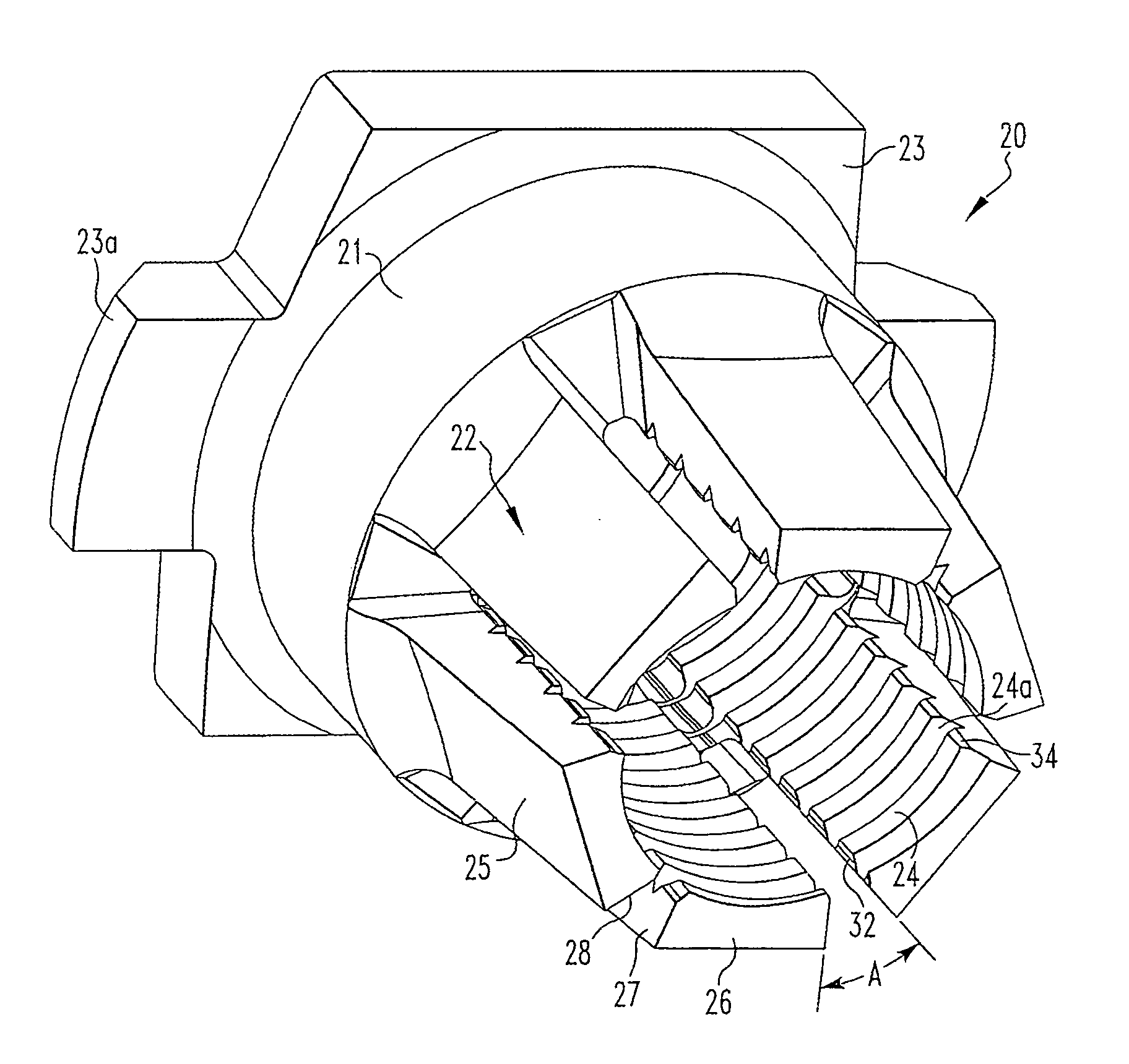
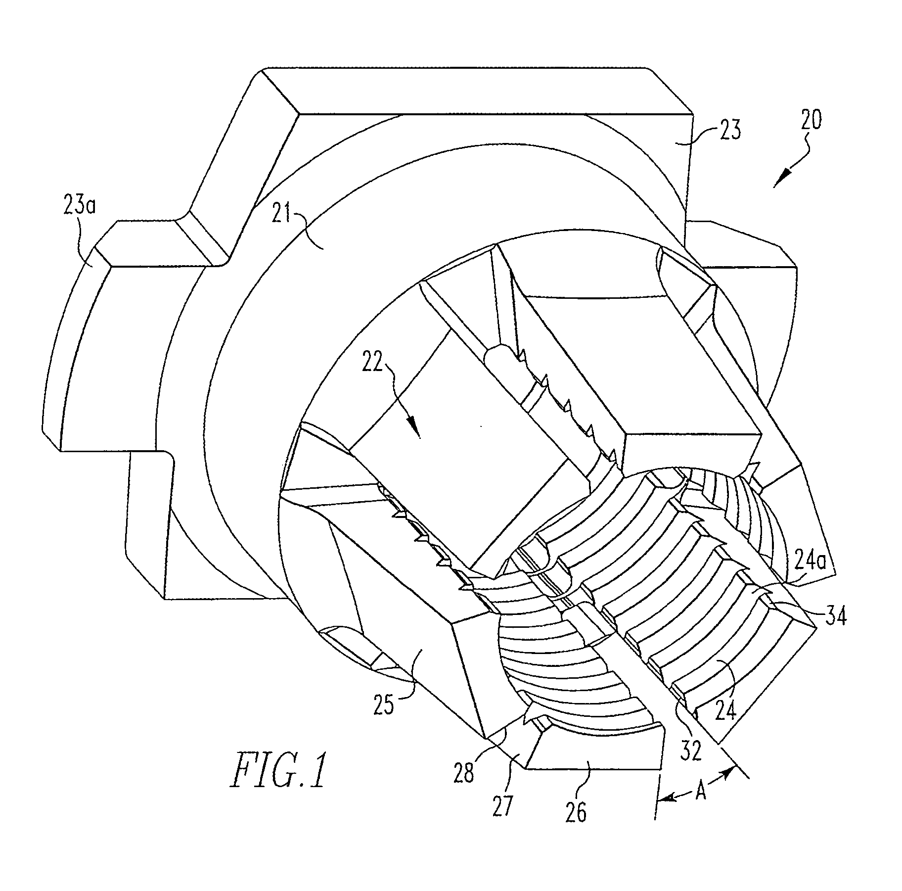
[0005] The present invention provides a beam nut construction and arrangement which addresses the problems associated with prior beam nut configurations. The invention is embodied in a locking beam nut having a plurality of circumferentially spaced resilient locking beams that are specifically configured to improve the performance and quality of the nut, and at the same time reduce manufacturing fabrication costs. The nut has unique features that provide substantially higher reuse cycles without rapid deterioration of the prevailing torque. The design allows for high reuse by lowering and reducing stress concentrations of a deflecting beam. The beam nut design of the present invention utilizes flat beams on the exterior portion of each beam, and a unique inside surface to substantially distribute the bending load through the length much more evenly, thus reducing stress concentrations. This is accomplished by incorporating an inside surface configuration wherein the internal threads at the junction of adjacent slotted beams are angled radially inwardly. This is in stark contrast to previous designs where the threads were 90° to the slotted beams. The angled radially inwardly inside beam configuration provides for a substantially “V-shaped” internal slot length that travels the full length of the beam, and, in certain applications can continue through the entire length of the nut. The V-shaped internal slot has the capability to improve cycle life or reusability performance due to the fact that the cantilevered beam now approaches the characteristics of a true rectangular beam.
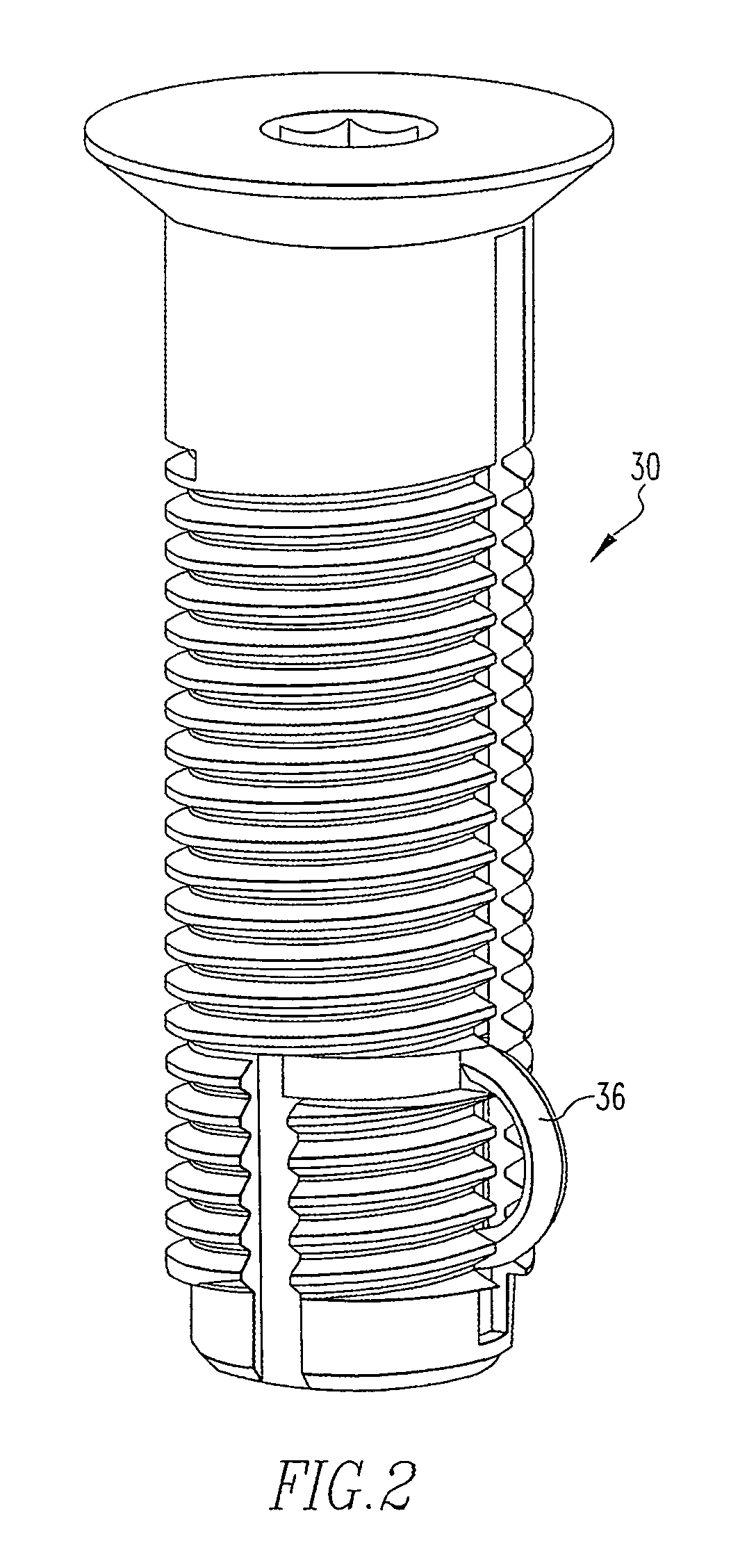
[0006] The internal V-shaped slot also eliminates the probability of the holdout spring on the bolt from becoming wedged into the slot by supplying an angled slope wide enough to act as a detent and not capture the holdout spring. A secondary locking system is added to provide additional prevailing torque and is accomplished during installation and removal of the beam nut wherein the holdout spring ratchets into each beam V-shaped slot whereby the additional friction contributes to increased prevailing torque.
[0007] A significant manufacturing improvement is realized with the internal V-shaped slot by streamlining and removing a series of costly operations in producing the beam nut previously required. The invention is produced by utilizing a heading procedure to form V-shaped slots from the exterior surface of a nut blank facing inward toward an external flat beam surface. Next a tap drilling operation commences wherein the tap drill removes the core and the apex of the external V form thereby forming the individual beams. The internal V-shaped slots are then formed by a broaching procedure and the nut is then threaded to complete the manufacturing process. This is in stark contrast to prior systems which required the tapping of the internal threads, then a slotting operation to form individual beams, which resulted in burrs forming in the internal threads of the nut. A subsequent retapping operation was necessary to remove the burrs. The method for manufacturing the present invention eliminates the beam slotting operation, double tapping and the deburring operations.

Problems solved by technology

This is in stark contrast to prior systems which required the tapping of the internal threads, then a slotting operation to form individual beams, which resulted in burrs forming in the internal threads of the nut.

Method used


Image

  • Lock nut member
  • Lock nut member
  • Lock nut member

Examples


Embodiment Construction

[0018] The present invention is an improvement in the construction and operation of known locking beam nuts or lock nuts and, in particular, of the lock nut shown and described in U.S. Pat. No. 5,088,868. Lock nuts of this kind are generally of a one-piece construction. As shown in FIG. 1, each lock nut 20 has a non-deflectable or rigid body portion 21 and a plurality of locking segments or beams 22. Each beam is formed integrally with the body portion 21 and extends axially therefrom. The body portion 21 has an internal axial opening extending completely through it. The opening is threaded so as to receive the, external threads of a bolt or like part or fastener. The body portion 21 may also have a plurality of flat wrenching surfaces (not shown) along its external surface. Lock nut 20 also includes a flange 23 adjacent the body portion 21 opposite from beams 22. Flange 23 may have a plurality of positioners 23a which are used for alignment purposes in a cassette or the like.

[0019...


PUM


Abstract

A threaded locking beam nut having a plurality of locking beams configured such that the inside edge surface of each locking beam has a radially inwardly angled surface thereby forming substantially a V-shaped channel between adjacent beams.

Description

CROSS REFERENCE TO RELATED APPLICATIONS [0001] This application is a divisional application of U.S. Ser. No. 10 / 410,078, filed Apr. 9, 2004.BACKGROUND OF THE INVENTION [0002] The present invention relates to lock nuts having a plurality of resilient locking segments which deflect in a manner similar to that of a beam, and, more particularly, to a construction of the locking segments wherein the internal threads at the junction of adjacent beams are angled radially inward, thereby forming a V-shaped internal slot. The present invention also is directed to a new method of manufacturing the lock nut. [0003] The present invention is an improvement in the design of a locking beam nut described and disclosed in U.S. Pat. No. 5,088,868. The locking beam nut of the '868 patent discloses a design having a plurality of circumferentially-spaced resilient locking beams that were specifically configured to prevent any accumulated debris from preventing a desired deflection of the beams. The beam...

Claims


Application Information

Patent Timeline
IPC IPC(8): F16B37/00F16B39/286
CPCF16B39/286F16B37/00
Inventor COSENZA, FRANK J.HAYLOCK, LUKE L.
Owner ALCOA GLOBAL FASTENERS
Learn More