Glass substrate for display and manufacturing method thereof

a technology of glass substrate and manufacturing method, applied in glass tempering apparatus, furniture, instruments, etc., can solve the problems of high production cost, difficult to solve ultra-small scratches on glass surface by grinding,

Inactive Publication Date: 2005-02-03
NIPPON ELECTRIC GLASS CO LTD
View PDF3 Cites 27 Cited by
  • Summary
  • Abstract
  • Description
  • Claims
  • Application Information

AI Technical Summary

Benefits of technology

[0010] The object of the present invention is to provide a glass substrate with a high grade of the surface where circuit disconnection or short circuit hardly takes place even if it is not ground, and to provide a manufacturing method thereof.

Problems solved by technology

However, if grinding is carried out, it causes a problem of production cost up.
Further, in recent years, along with the advancement in high fineness and precision of a display, ultra small scratches on the glass surface by grinding become challenging concerns to be solved.
However, there sometime occurs a trouble in an unground glass substrate that patterns are disconnected or short-circuited in a film formation step carried out thereafter.

Method used

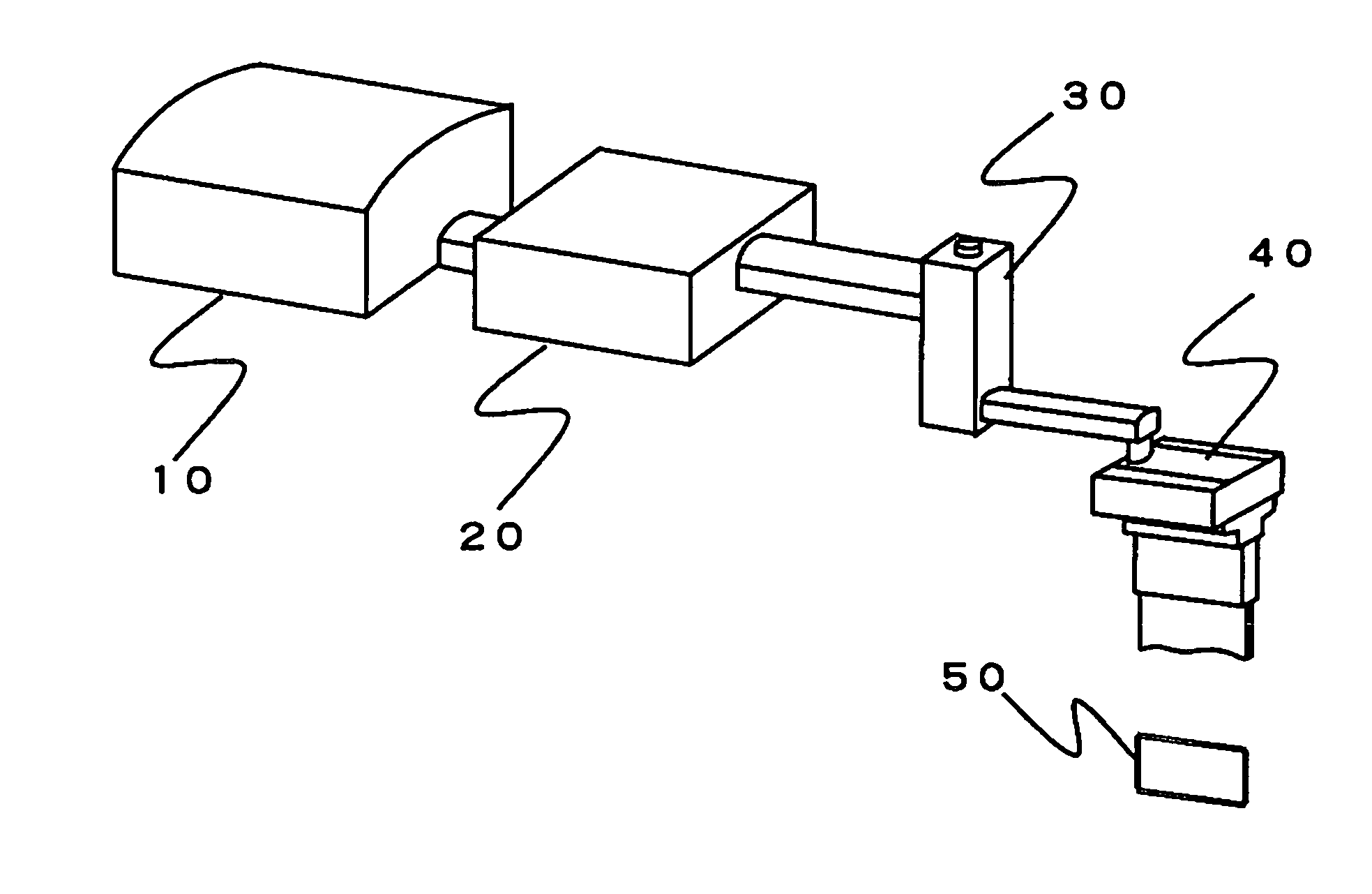
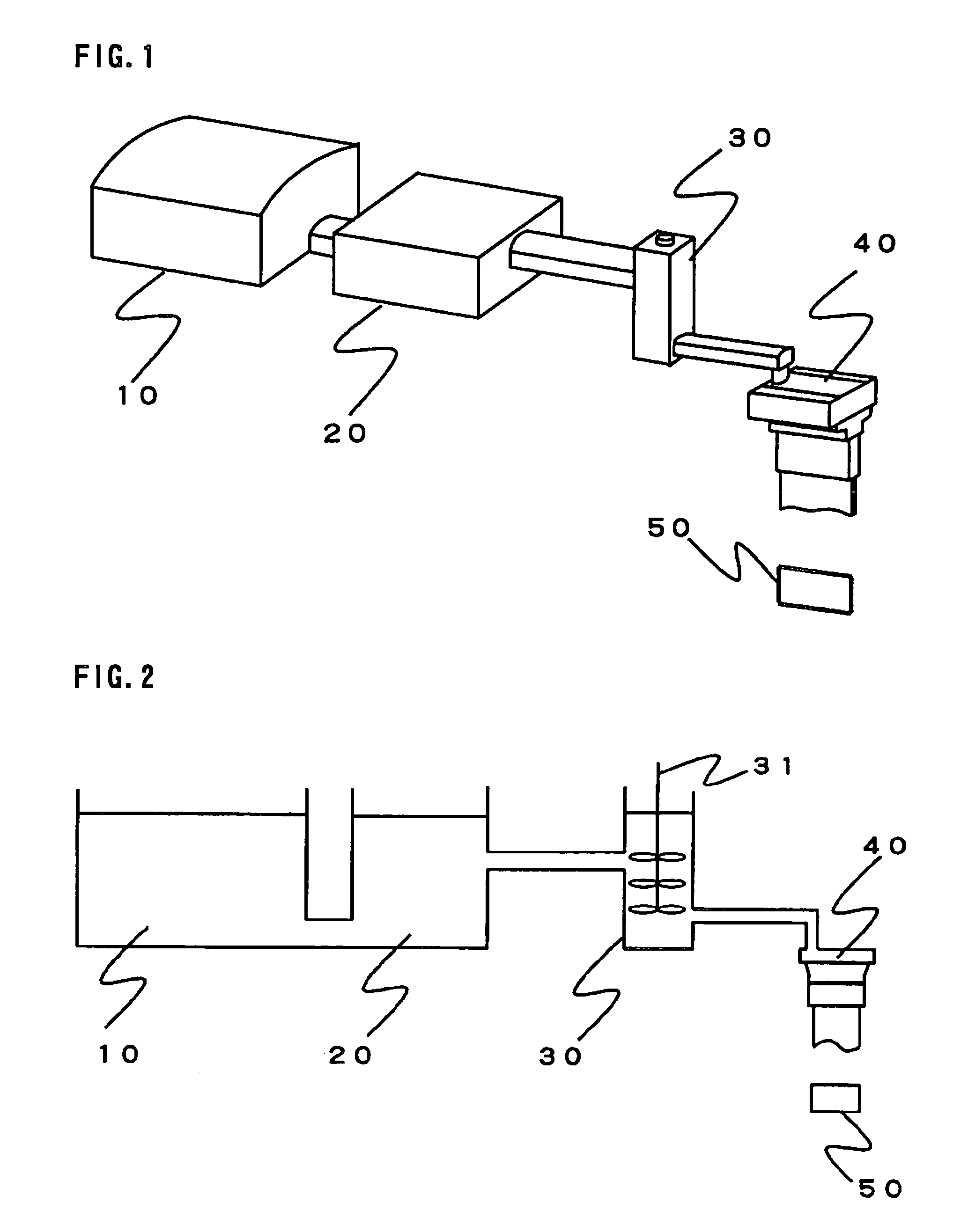
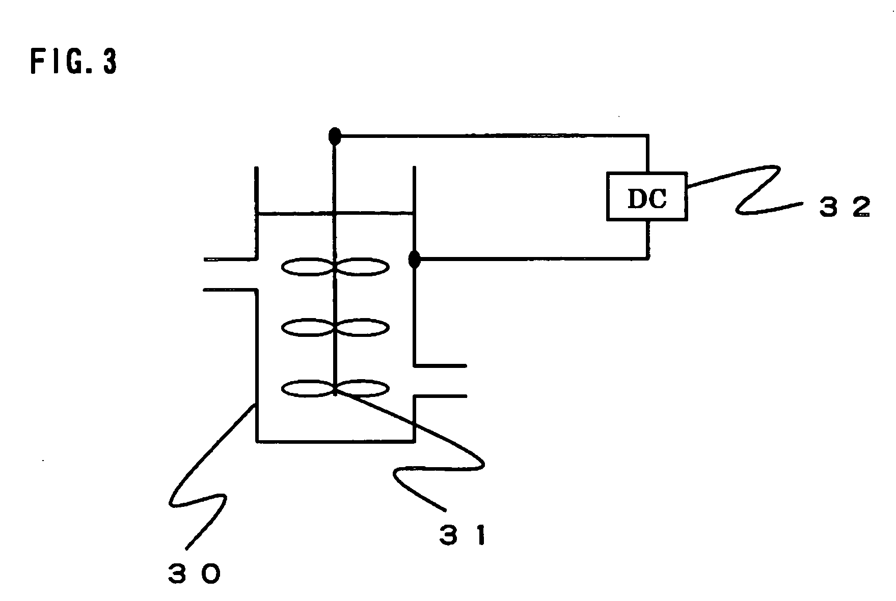

Image

  • Glass substrate for display and manufacturing method thereof
  • Glass substrate for display and manufacturing method thereof
  • Glass substrate for display and manufacturing method thereof

Examples


Embodiment Construction

[0017] The causes for formation of projections in a glass substrate are supposed as follows.

[0018] In the case a platinum group element or a platinum group element alloy is used for a melting furnace or a forming apparatus, it is taken in the molten glass and forms platinum group element stones. At the time of forming the molten glass into a glass substrate, the molten glass is extended into a prescribed thickness; however, the platinum group element stones existing in the glass are solid and therefore scarcely extended. Accordingly, the portions where the platinum group element stones exist have a thickness increased to the extent that the thickness of the platinum group element stones is not made thin. The increase of the thickness is finally moderated owing to the viscous fluidity and elongation of glass in the surrounding of the platinum element stones. However, in the case the platinum group element stones exist near the glass substrate surface, since the amount of the glass i...


PUM

PropertyMeasurementUnit
thicknessaaaaaaaaaa
surface areaaaaaaaaaaa
temperatureaaaaaaaaaa

Abstract

The invention provides a glass substrate for a display, having a surface area of 0.1 m2 or more and a thickness of 2.5 mm or less and to be used for a display. The glass substrate has surface projections of 2 pcs / m2 or less, and the surface is not ground

Description

BACKGROUND OF THE INVENTION [0001] 1. Field of the Invention [0002] The invention relates to a glass substrate for a display to be used for a liquid-crystal display or a plasma display and a manufacturing method thereof. [0003] 2. Description of the Related Art [0004] Conventionally, as a display substrate to be used for a liquid-crystal display or a plasma display, a rectangular glass substrate has been widely used. [0005] Generally, a glass substrate for a display can be obtained by blending raw materials; melting the blended raw materials using melting facilities; forming the melt into a plate-like shape by a slot down draw method, an over flow down draw method, a float method, a roll out method or the like; and cutting the plate-like product (e.g., Japanese Patent Laid-Open 2001-122637). [0006] Additionally, for the purpose of stain prevention for the glass, the portions to be brought into contact with the molten glass in the production facilities are made of a platinum group el...

Claims


Application Information

Patent Timeline
Patent Type & Authority Applications(United States)
IPC IPC(8): G02F1/1333C03B5/167C03B5/18C03B5/425C03B17/06C03C3/083C03C3/085C03C3/087C03C3/091C03C3/093G02F1/13H01J11/34H01J11/44H01J17/16
CPCC03B5/1675C03B5/1677C03B5/425H01J11/34C03C3/091G02F2001/133302H01J11/10C03B17/06G02F1/133302Y02P40/57G02F1/13
Inventor TAKASE, HIRONORITAKAYA, TATSUYA
Owner NIPPON ELECTRIC GLASS CO LTD
Why Eureka
Try Eureka