Stent delivery and deployment system

a stent and vascular wall technology, applied in the field of stent delivery and deployment system, can solve the problems of inaccurate deployment at the target site, reduced vascular wall support at the site of deployment, and difficult use of conventional self-expansion stent delivery system,

Inactive Publication Date: 2005-02-03
SALVIAC
View PDF99 Cites 176 Cited by
  • Summary
  • Abstract
  • Description
  • Claims
  • Application Information

AI Technical Summary

Benefits of technology

[0003] Stents are commonly used in the repair of aneurysms, as liners for vessels, or to provide mechanical support to prevent the collapse of stenosed or occluded vessels. Stents are typically delivered in a compressed state to a specific location inside the lumen of a vessel or other tubular structure, and then deployed at that location in the lumen to an expanded state. A stent has a diameter in its expanded state which is several times larger that the diameter of the stent in its compressed state. Stents are also frequently deployed in the treatment of atherosclerotic stenosis in blood vessels, especially after percutaneous transluminal coronary angioplasty (PTCA) procedures, to improve the results of the procedure and to reduce the likelihood of restenosis.
[0006] Delivery systems for self expanding stents generally comprise an inner component or core about which the stent is positioned in a retracted or reduced diameter and an outer sheath surrounding the stent. The stent is deployed by retracting the outer sheath relative to the inner component. This has the effect of removing the constraint on the stent which, on release, expands into an increased diameter deployed configuration. The procedure is controlled by a clinician by manipulating various components outside of the vasculature.

Problems solved by technology

Conventional self expanding stent delivery systems suffer from the considerable disadvantage that they are difficult to use, even for a very skilled clinician.
Even small irregular movements by the clinician may result in inaccurate deployment at the target site.
Inaccurate deployment of a stent may diminish the effectiveness of supporting the vascular wall at the site of deployment.
There are particular difficulties in navigating complex stent delivery systems through tortuous arterial passageways, especially a carotid artery, a superficial femoral artery or a renal artery.

Method used


Image

  • Stent delivery and deployment system
  • Stent delivery and deployment system
  • Stent delivery and deployment system

Examples


Embodiment Construction

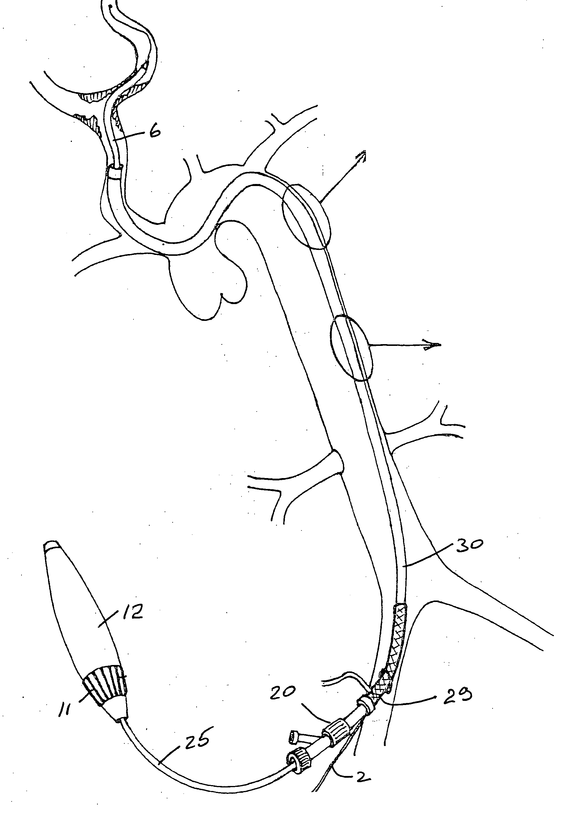
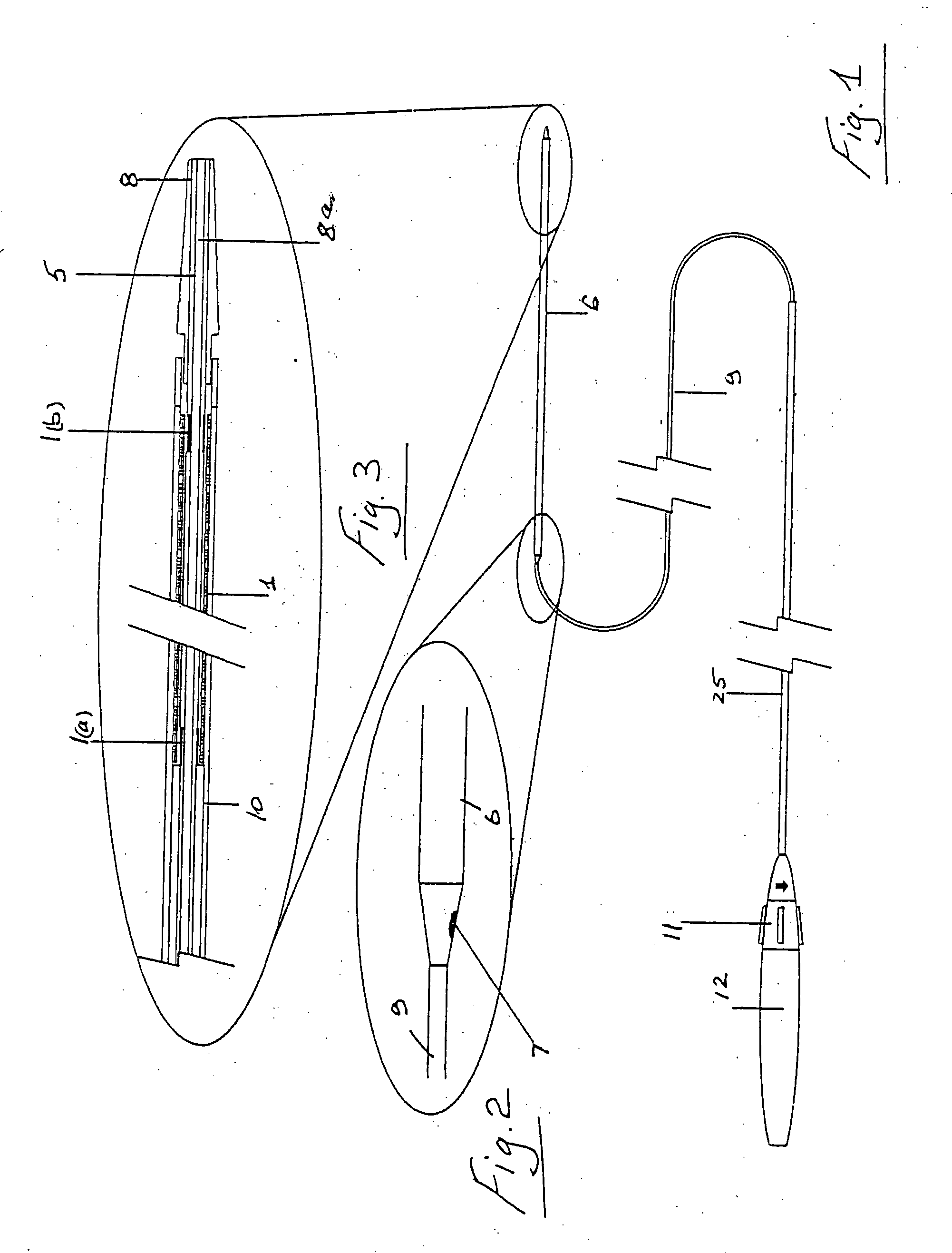
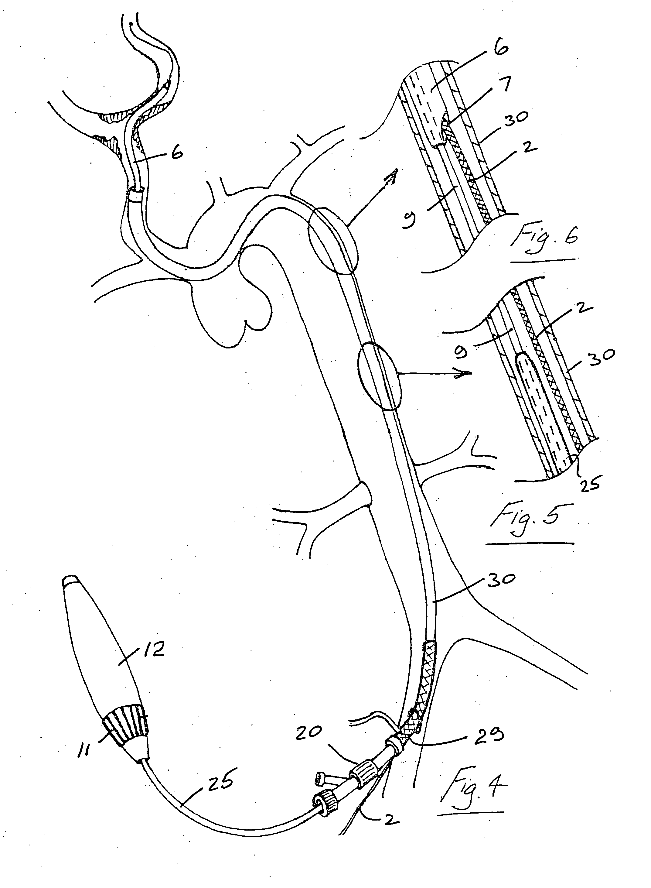
[0112] Referring to the drawings and initially to FIGS. 1 to 13 thereof there illustrated a delivery and deployment system for a self expanding stent 1. The system is in this case configured for use with a guidewire 2 of the rapid exchange type with a distal tip 3.

[0113] The system comprises an inner core 5 about which the stent 1 is located and a catheter shaft 9 having a distal sheath 6 which retains the stent 1 in a compressed configuration during delivery through the vasculature of a patient to a deployment site as illustrated for example in FIG. 9(a). To deploy the stent 1 the sheath 6 is drawn proximally relative to the inner core 5 and the stent expands into a deployed configuration as illustrated, for example in FIG. 9(b). The sheath 6 has a rapid exchange guidewire exit port 7.

[0114] The delivery system has a distal tip 8 with a guidewire lumen 8a. Marker bands 1a, 1b are provided for visualisation of the inner core 5 at the proximal and distal ends of the stent 1.

[0115]...


PUM


Abstract

A delivery system for delivery and deployment of a self expanding stent 1 especially in an arterial vessel with a tortuous passageway leading thereto comprises a catheter shaft 9 with a distal sheath 6. An inner core 5 is fixed to a larger diameter outer core 10, the difference in diameter providing an abutment. To deploy the stent 1, the sheath 6 is drawn proximally relative to the inner core 5, the proximal end of the stent 1 is engaged by the abutment and the stent 1 expands as it is uncovered by the sheath 6. The system includes a stabiliser tube 25 to which the inner core 5 is fixed, at least during the deployment of the stent 1.

Description

[0001] The invention relates to a delivery system for delivery and deployment of a stent to a desired vascular location. [0002] Vascular intervention is today undertaken to treat a large number of diseases that had heretofore been treated by surgery. Stents are used widely in a number of applications to provide structural support to vessels that are being treated. [0003] Stents are commonly used in the repair of aneurysms, as liners for vessels, or to provide mechanical support to prevent the collapse of stenosed or occluded vessels. Stents are typically delivered in a compressed state to a specific location inside the lumen of a vessel or other tubular structure, and then deployed at that location in the lumen to an expanded state. A stent has a diameter in its expanded state which is several times larger that the diameter of the stent in its compressed state. Stents are also frequently deployed in the treatment of atherosclerotic stenosis in blood vessels, especially after percuta...

Claims


Application Information

Patent Timeline
Patent Type & Authority Applications(United States)
IPC IPC(8): A61F2/01A61F2/84
CPCA61F2/013A61F2/95A61F2/966A61F2230/0006A61M2025/0175A61M2025/0675A61F2002/9517A61F2/9517
Inventor HORAN, STEVENVALE, DAVIDMOLLOY, SHANEBRADY, EAMONKEEGAN, MARTIN
Owner SALVIAC
Why Eureka
Try Eureka