[0014] In an exemplary embodiment, an
infrared measurement technique is used, as presented by Hoppe and Wolf in “IR Instrument For Gas Property Determination In Industrial Processes”, IGRC 2001, Amsterdam, 6.11.2001. This allows the measurement to be carried out very quickly and for the measured values to be available in real time. In this context, it is proposed that the
infrared absorption by the fuel gas be determined in two different spectral regions. It is proposed that the absorption be determined in a first spectral region around 3.5 μm, which reacts primarily to the ethane,
propane and
butane content, and in a second spectral region around 7.9 μm, where the absorption substantially reacts to the
methane content of the measurement gas. The cross-sensitivity between the spectral regions is low and can easily be corrected if necessary. In this way, it is possible for the C2+-
alkane content to be determined continuously and rapidly. In principle, measurement only in the C2+
alkane-sensitive spectral region around 3.5 μm is also sufficient to carry out the method according to the invention. This is quite sufficient for qualitative determination of a changed fuel-
gas composition and for an appropriate reaction; measurement in both
wavelength regions is more accurate and is in fact required for quantitative information to be obtained. In one embodiment of the method, the
infrared absorption is additionally determined in a
wavelength region around 4.3 μm, which reacts primarily to the CO2 content. It is also possible to extend the method to other spectral regions which react sensitively to specific gas components. In a further preferred refinement, the
thermal conductivity is measured as a measure of the
nitrogen (N2) content. Where appropriate, using cross-sensitivity correction algorithms, it is in this way possible to determine the fuel-
gas composition very accurately, continuously and in real time. This also allows the calorific value or the
Wobbe index to be determined.
[0016] It is known from EP 1 199 516 to make a central axial air flow variable in premix burners. In the context of the method according to the invention it is possible to control this axial flow as a function of the fuel properties determined. For example, as the C2+-alkane content of the fuel gas rises, it is possible to make the axial flow more intensive, in order thereby to avoid the risk of flashback into the burner interior.
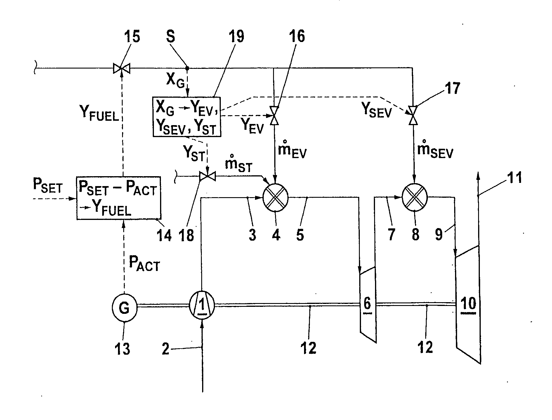
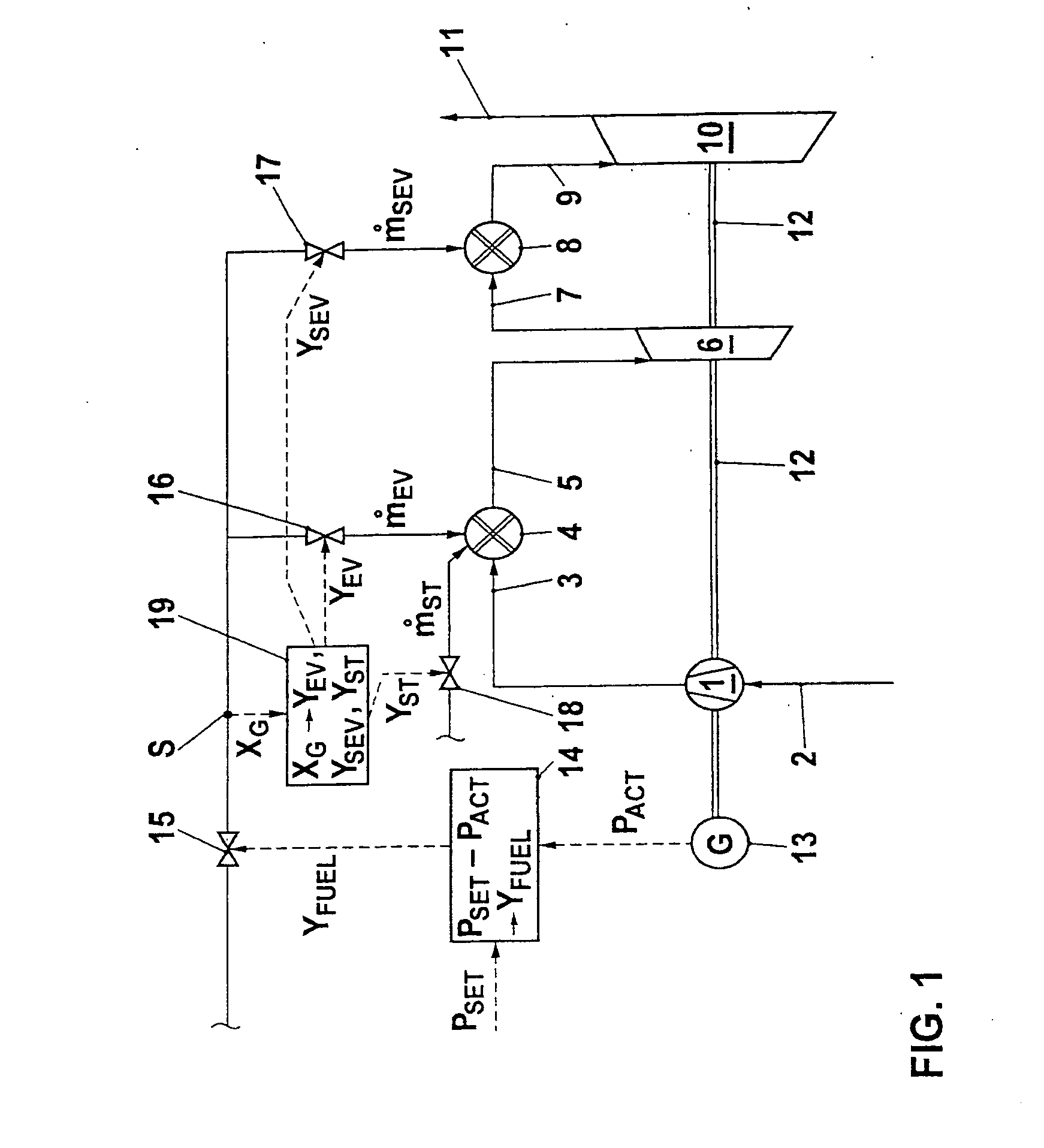
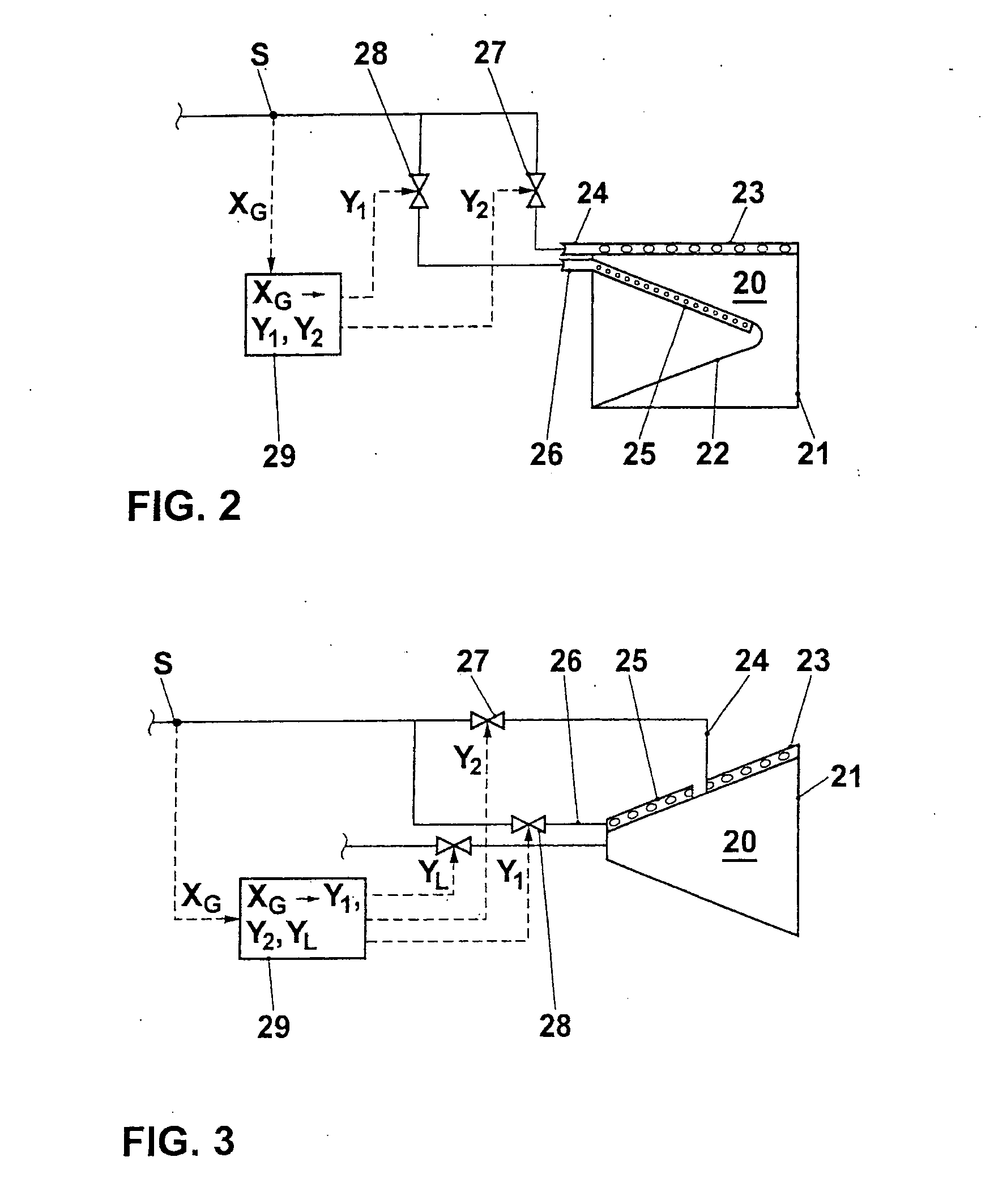
[0017] Premix burners of the types which are currently used often have a plurality of fuel feeds to which fuel can be supplied independently of one another, for example for the independent application of
pilot fuel, which is burnt in a
diffusion combustion mode, and premix fuel. Burners of this type are described, for example, by WO 01 / 96785, EP 193 838, EP 108 361, WO 00 / 12936, EP 945 677, or EP 321 809. The distribution of the fuel can be varied as a function of the measured fuel properties, in order on the one hand to ensure sufficient
flame stability and at the same time to avoid flashback or component overheating and to keep the emission levels approximately constant.
[0020] A further control action possibility is for the gas turbine group to have means for cooling the working medium upstream of the compressor or in the compressor or between compressor stages. More intensive cooling reduces the temperature of the combustion air and thereby lowers the ignitability. Furthermore, it is known to realize the cooling by introducing a liquid, for example water, upstream of the compressor or into the compressor, in which case, for example, drops of water penetrate into the compressor and are evaporated during the compression. In recent times, this solution has become popular under the names wet compression, high
fogging or overfogging, and has been described, for example, in U.S. Pat. No. 2,786,626, while FR 1,563,749 indicates the positive effects on the performance data of a gas turbine group. The humidification of the combustion air which results further reduces the ignitability.

