Method and apparatus for the integration of electronics in textiles

a technology of electronics and textiles, applied in weaving, non-metallic protective coating applications, semiconductor/solid-state device details, etc., can solve the problems of affecting the use properties of textiles, limiting the integration of electronics into textile surroundings, and commercially available electronic modules in textile environments are not very flattering, etc., to achieve simple and secure mechanical connection of components, high mechanical and chemical resistance of the apparatus, and simple mechanical connection

Inactive Publication Date: 2005-02-10
INFINEON TECH AG
View PDF8 Cites 108 Cited by
  • Summary
  • Abstract
  • Description
  • Claims
  • Application Information

AI Technical Summary

Benefits of technology

[0013] On the other hand, the second encapsulation, which, like the first encapsulation, does not have to surround the component completely, does not have its main function in the mechanical and possibly chemical protection of the contact point region. Instead, the second encapsulation is designed in such a way that it permits simple and secure mechanical connection of the component to the textile material. Thus, the requirements which have to be placed on the second encapsulation are different from those of the first encapsulation, so that more suitable materials can be selected for the purposes of the mechanical connection between the component and the textile material.
[0014] The first encapsulation preferably surrounds the component completely. If the component is, for example, a circuit board fitted with individual electronic components, then the first encapsulation surrounds both the individual electronic components and the contact points of the component, to which electric conductor tracks or electrically conductive wires are connected. Such complete encapsulation of the electronic component with the connecting region of the electric feed lines ensures high mechanical and chemical resistance of the apparatus according to the invention.
[0015] The second encapsulation preferably surrounds the component with the first encapsulation completely. The component, which, for example, is surrounded by the first hard encapsulation only in its contact point regions, is thus preferably surrounded completely by the second encapsulation. Since the second encapsulation is designed in such a way that it permits simple mechanical connection of the component contained to the textile material, the complete second encapsulation permits a particularly good possibility of integration

Problems solved by technology

Previous approaches to integrate electronics into textile surroundings are restricted to sewing in commercially available electronic modules, such as sewing in small electronic computers (palmtops, mobile telephones, GPS systems or MP3 players) and “laying” conventional connecting cables in “textile cable ducts” in clothing specifically tailor-made for that purpose.
However, such attempts to integrate electronic components in a textile environment leads to a cons

Method used


Image

  • Method and apparatus for the integration of electronics in textiles
  • Method and apparatus for the integration of electronics in textiles
  • Method and apparatus for the integration of electronics in textiles

Examples


Embodiment Construction

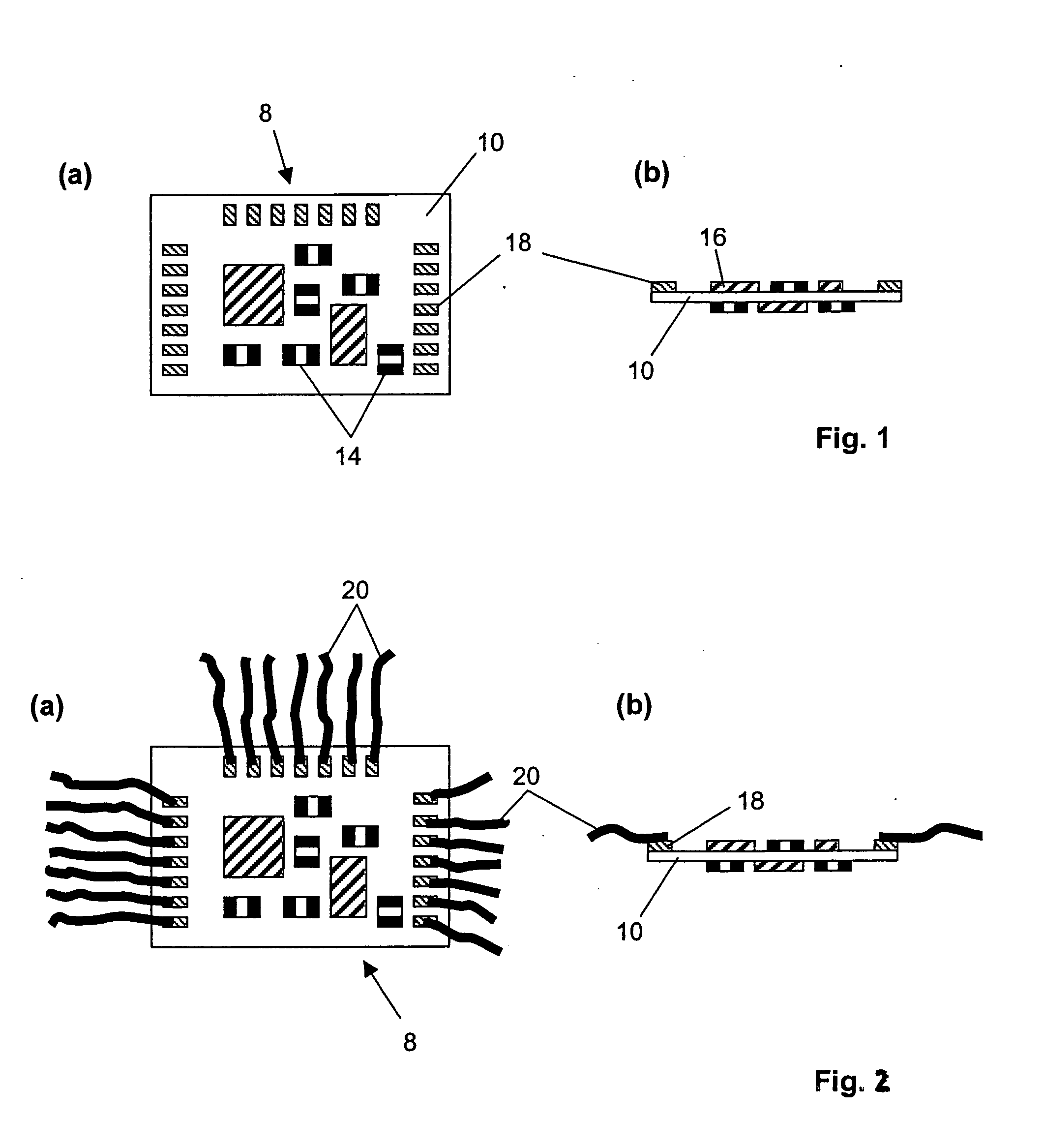
[0038] In FIG. 1, an electronic component 8 which is to be integrated into a textile environment is illustrated in plan view (a) and in sectional view (b). The electronic component 8 has a single-layer or multilayer epoxy circuit board 10. A ceramic board or a similar supporting apparatus can also be used equally well. On the circuit board 10 there are, for example, a large number of individual passive 14 and active 16 components or electronic modules. The power supply and the data input and output are carried out via a large number of preferably regularly spaced contact points 18 which, for example, are formed as bond pads or soldering platforms. The electronic component 8 is preferably as small as possible, in order in this way to stiffen only a small area in the textile environment and—as shown in the sectional view FIG. 1(b)—is fitted on both sides if necessary.

[0039] In FIG. 2, the electronic component 8 according to FIG. 1 is shown in plan view (a) and sectional view (b), thi...


PUM

PropertyMeasurementUnit
Temperatureaaaaaaaaaa
Diameteraaaaaaaaaa
Diameteraaaaaaaaaa

Abstract

Apparatus having at least one textile material in which at least one flexible, wire-like and/or thread-like electric conductor is arranged, at least one electronic component which has at least one electrically conductive contact point which is connected electrically to the conductor, at least a first hard encapsulation which covers and mechanically stabilizes at least the contact point of the component, and at least a second encapsulation, which is designed such that it permits a mechanical connection of the component to the textile material, wherein the second encapsulation comprises a silicone, a polyurethane and/or a textile adhesive.

Description

CROSS-REFERENCE TO RELATED APPLICATION [0001] This application is a continuation of International Patent Application Serial No. PCT / EP02 / 13746, filed Dec. 4, 2002, which published in German on Jul. 24, 2003 as WO 03 / 059101, and is incorporated herein by reference in its entirety.FIELD OF THE INVENTION [0002] The present invention relates to a method and apparatus for the integration of electronics in textiles. BACKGROUND OF THE INVENTION [0003] The integration of electronic systems in a textile environment has achieved increasing importance in recent times. For example, an increasing demand for textile clothing and accessories has to be recorded which, in addition to their traditional functions, such as a thermal or protective effect and status symbol characteristics, can also fulfill additional functions such as healthcare, personal safety and communication. Numerous conceivable applications of “intelligent clothing” (smart clothes) can be implemented by means of the integration of...

Claims


Application Information

Patent Timeline
IPC IPC(8): A41D13/00A41D1/00A41D31/00D03D15/00H05K3/28
CPCA41D1/002H05K2201/029H05K3/284H05K1/038
Inventor JUNG, STEFANLAUTERBACH, CHRISTL
Owner INFINEON TECH AG
Why Eureka
Try Eureka