Low jitter high phase resolution PLL-based timing recovery system

a high phase resolution, low jitter technology, applied in the direction of electronic switching, electrical equipment, pulse automatic control, etc., can solve the problems of noise corruption, large filter quality factors, and general impracticality of transmitting sampling clock information from a transmitted datastream

Inactive Publication Date: 2005-02-10
AVAGO TECH INT SALES PTE LTD
View PDF4 Cites 22 Cited by
  • Summary
  • Abstract
  • Description
  • Claims
  • Application Information

AI Technical Summary

Benefits of technology

[0019]FIG. 5 is a simplified, semi-schematic block diagram of a divide-by-M model which illustrates VCO jitter averaged over M cycles; and
[0020]FIG. 6 is a simplified, semi-schematic block diagram of a Gray code MUX suitable for implementation in a PLL according to the invention.

Problems solved by technology

Given the bandwidth constraints imposed on most modern data communications systems, it is generally impractical to transmit sampling clock information separate from a transmitted datastream.
Noise corruption occurs, for example, in satellite transceivers where intelligence signals, weak with respect to noise components, must be detected by coherent demodulation.
However, in most applications, the required filter bandwidth is several orders of magnitude smaller than typical carriers, thereby demanding relatively large filter quality factors (Qs).
Jitter can arise from many sources, including inadvertent injection of signals from other parts of a circuit through the power supply.
The inherent thermal and / or shot noise of the active and passive devices that make up a VCO cell, and, particularly, the sub-harmonic frequencies of the clock signal itself mixing into the desired output signal.
However, it is well recognized that in a VCO design with multiple clock phase outputs, the opportunities for random variation in the triggering edges, due to inter-stage interaction, RMS voltage noise, cycle-to-cycle jitter, and the like increases.
In addition, for large numbers of clock phases produced by a VCO, it becomes difficult to design a VCO which does not exhibit multiple modes of oscillation.
Thus, even though ring oscillators have been proposed as suitable candidates for implementation as low-noise voltage-controlled oscillators in high-performance PLL systems, their implementation has been limited because of their generally characterized “high” phase noise.

Method used


Image

  • Low jitter high phase resolution PLL-based timing recovery system
  • Low jitter high phase resolution PLL-based timing recovery system
  • Low jitter high phase resolution PLL-based timing recovery system

Examples


Embodiment Construction

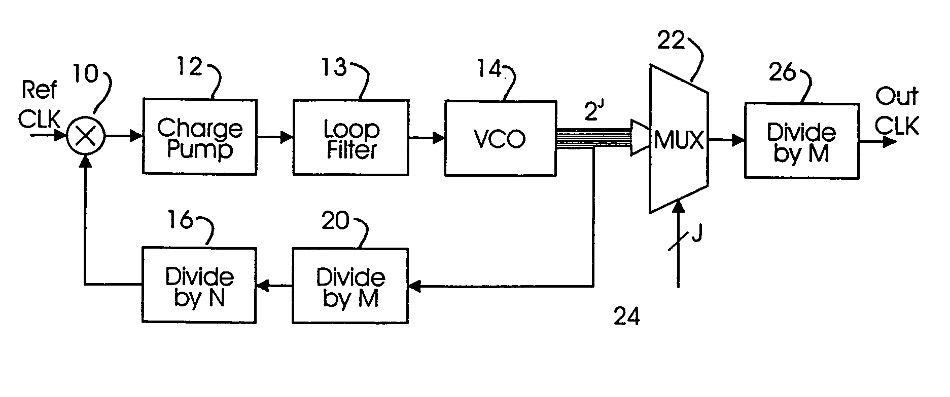
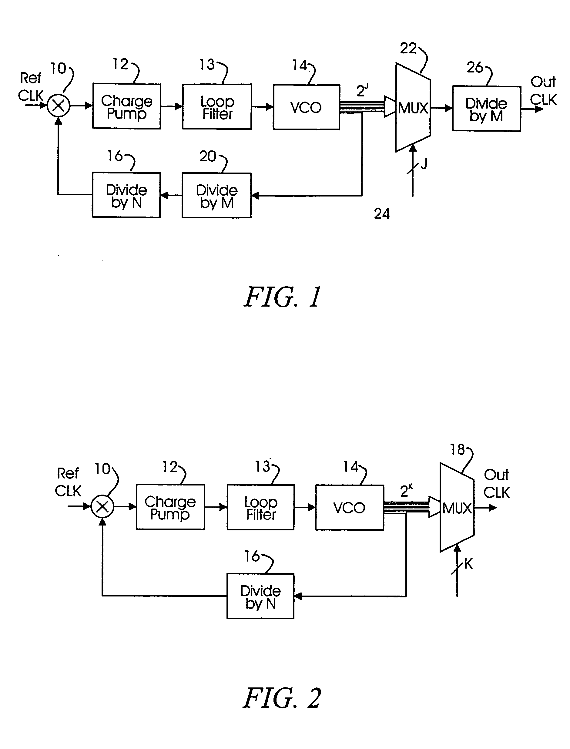
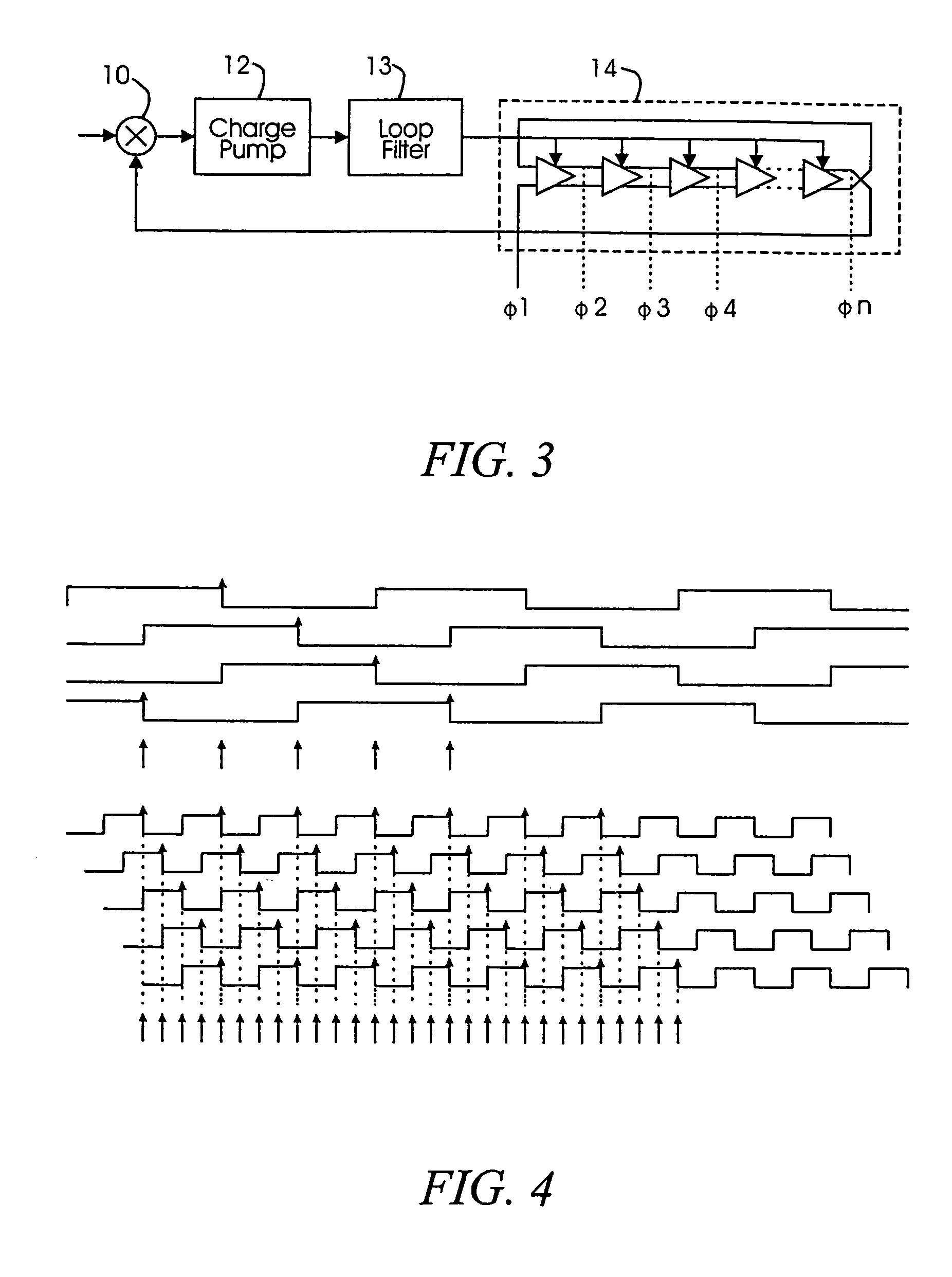
[0021] In accordance with the present invention, a low jitter, high phase resolution PLL employs a voltage controlled oscillator (VCO) which operates at a characteristic frequency M times higher than the characteristic frequency typically required for an output clock signal. Operating a multi-phase VCO at such a higher output frequency reduces the number of output phases which must be taken from the VCO by the same scale factor M. In addition to reducing the number of VCO output phases, the physical size of selection circuitry, such as a phase control MUX is also reduced by the scale factor M, while the number of phase control lines, controlling operation of the phase control MUX, are also able to be reduced by a scale factor related to the scale factor M.

[0022] Since the number of VCO phase stages are able to be reduced, power supply and substrate noise injection is reduced as a consequence, resulting in a lower jitter VCO design. Because the number of output phases taken from a m...


PUM


Abstract

A low jitter, high phase resolution phase lock loop incorporating a ring oscillator-type VCO is designed and constructed to operate at a characteristic frequency M times higher than a required output clock frequency. Multi-phase output signals are taken from the VCO and selected through a Gray code MUX, prior to being divided down to the output clock frequency by a divide-by-M frequency divider circuit. Operating the VCO at frequencies in excess of the output clock frequency, allows jitter to be averaged across a timing cycle M and further allows a reduction in the number of output phase taps, by a scale factor M, without reducing the phase resolution or granularity of the output signal.

Description

CROSS-REFERENCE TO RELATED APPLICATION(S) [0001] This application is related to co-pending provisional application Ser. No. 60 / 110,557, filed Dec. 7, 1998, entitled “LOW JITTER HIGH PHASE RESOLUTION PLL FOR GIGABIT ETHERNET”, commonly owned by the Assignee of the present invention, the entire contents of which are expressly incorporated herein by reference.FIELD OF THE INVENTION [0002] The present invention is directed to high speed timing recovery systems and, more particularly, to a low jitter, high phase resolution timing recovery system. BACKGROUND OF THE INVENTION [0003] The past several years have witnessed a dramatic increase in the capabilities of high-speed, high-density broadband data communication systems. Pertinent such systems range anywhere from broadcast or cablecast HDTV systems, local area and wide area (LAN, WAN) systems for multimedia, fiber to the home (FTTH) applications and board-to-board interconnections in exchange systems and computers. [0004] In any one of ...

Claims


Application Information

Patent Timeline
Patent Type & Authority Applications(United States)
IPC IPC(8): H03L7/089H03L7/099H03L7/183
CPCH03L7/0891H03L7/183H03L7/0996
Inventor WAKAYAMA, MYLESJANTZI, STEPHEN A.KIM, KWANG YOUNGCHEUNG, YEE LING "FELIX"TONG, KA WAI
Owner AVAGO TECH INT SALES PTE LTD
Why Eureka
Try Eureka