Method for manufacturing coil-embedded dust core and coil-embedded dust core

a technology of dust core and coil, which is applied in the field of manufacturing coilembedded dust core and coilembedded dust core, can solve the problems of coil damage, difficult compression,

Inactive Publication Date: 2005-02-10
TDK CORPARATION
View PDF5 Cites 15 Cited by
  • Summary
  • Abstract
  • Description
  • Claims
  • Application Information

AI Technical Summary

Benefits of technology

[0011] When the inventors made various studies to solve the above-described problems, the inventor found out that the position of the coil in the coil-embedded dust core and the position especially in the compacting direction have a large influence on inductance, and a variation of the inductance value is reduced by entirely equalizing the density of the green body. The inventors also confirm that it is easy and effective to reduce the amount of soft magnetic metal powder charged into the part corresponding to the winding section of the air-core coil more than the amount of the soft magnetic metal powder charged into the other part which is not corresponding to the winding section in order to equalize the density of the green body in the coil-embedded dust core entirely. Namely, the present invention is a method for manufacturing a coil-embedded dust core constructed by embedding an air-core coil having a winding section and end sections led out of the winding section in a green body, and characterized by including a step (a) of charging soft magnetic metal powder including an insulating material, composing the green body, so as to cover the air-core coil, and a step (b) of compacting the soft magnetic metal powder covering the air-core coil in an axial direction of the air-core coil, and characterized in that in the step (b), the soft magnetic metal powder is compacted while an amount of the soft metal powder charged into a part corresponding to the winding section is kept smaller than an amount of the soft magnetic metal powder charged into the other part that are not corresponding to the winding section, with an upper surface or a lower surface of the winding section as a reference.
[0012] Here, as the other part, the part corresponding to the hollow part of the air-core coil is cited. Namely, compacting is performed in the state in which more soft metal powder is charged into the part corresponding to the hollow part of the air-core coil than the part corresponding to the winding section. It is also preferable to charge a larger amount of soft magnetic metal powder into the parts corresponding to the corner parts of the green body and the surroundings of the end sections led out form the winding section than into the part corresponding to the winding section. Since the soft magnetic metal powder charged into the part corresponding to the winding section of the air-core coil (hereinafter, appropriately called “a coil part”) is easily compacted than the soft magnetic metal powder charged into the other part which is not corresponding to the winding section (hereinafter, appropriately called “a non-coil part”), the density of the coil part inevitably tends to be higher than that of the non-coil part, but by performing compacting in the state in which more soft magnetic metal powder is charged into the non-coil part than into the coil part in advance, the coil-embedded dust core with entirely uniform density can be obtained. According to the coil-embedded dust core with entirely uniform density, a variation in inductance value is reduced, and it becomes possible to obtain a predetermined inductance value with stability. Since the coil is metal, it is more difficult to compress than soft magnetic metal powder, and the coil is sometimes damaged if it is forcefully pressurized. However, according to the method proposed by the present invention, the coil-embedded dust core with entirely uniform density can be obtained without damaging the coil.
[0015] Further, the present invention provides a method for manufacturing a coil-embedded dust core in which an air-core coil is embedded in a green body with use of a die machine comprising a upper die set including an upper die and a top punch ascending and descending inside the upper die, and a lower die set including a lower die and a bottom punch ascending and descending inside the lower die. In concrete, in a step (a), soft magnetic metal powder including an insulation material, composing the green body, is charged into a cavity of the lower die equipped with a tubular member, which has a top portion in substantially the same shape as the plane shape of the air-core coil, in the bottom punch to be ascendable and descendable. In the following step (b), the air-core coil is placed concentrically with the tubular member in a state in which it ascends to a predetermined position, inside the cavity of the lower die with the soft magnetic metal powder being charged therein, and in a step (c), the upper die descends to the lower die, and further charging the soft magnetic metal powder into a cavity of the upper die so as to cover the air-core coil. In a step (d), the soft magnetic metal powder is compacted in the axial direction of the air-core coil by relatively lowering the top punch with respect to the bottom punch. Here, the air-core coil can be a coil made by winding a flat conductor, including a winding section being insulation coated and end sections led out of the winding section. With use of the coil with the flat conductor being wound around, the current capacity per volume can be increased, and further reduction in size of the coil-embedded dust core (reduction in height) is made possible.
[0016] Prior to the aforementioned step (a), it is effective to further include a step of controlling a relative position of the lower die, the bottom punch and the tubular member in a compacting direction according to thickness of the winding section of the air-core coil in the axial direction. This makes it possible to place the air-core coil at the center in the axial direction of the green body ultimately.
[0017] Further, in the aforementioned step (d), it is desired that the upper die, the lower die and the tubular member relatively descend to a predetermined position with respect to the bottom punch while a state in which the end sections of the air-core coil are held between the upper die and the lower die is kept, and in synchronism with the movement to relatively lower the top punch with respect to the bottom punch. This makes it possible to pressurize the soft magnetic metal powder in the vertical direction without damaging the end sections of the air-core coil.
[0019] It is desirable that the air-core coil is constructed by a rectangular wire. Further, it is effective to use a so-called terminal-integrated air-core coil, in which part of the air-core coil functions as a terminal section. Furthermore, the end sections of the air-core coil can be exposed to an outside of the green body from a center of side surface of the green body with a thickness direction of the green body as the reference. If the connection part is located inside the green body, a joint failure (including joint failure) easily occurs to the connection part during compression, and by making the end sections of the air-core coil as the terminal section, and exposing the end sections to the outside of the green body, the connection part can be placed outside. Thus, the coil-embedded dust core can be provided which hardly causes problems such as joint failure between the coil and the terminal section or insulation failure of the coil and terminal section with respect to the magnetic powder. In this specification, the connection part means the portion at which the components are electrically connected to each other, and the portion at which soldering is made with the external electrode such as a land pattern of the surface mounting substrate is called a terminal section. In order to expose the end sections of the air-core coil to the outside of the green body from the center of the side surface of the green body with the thickness direction of the green body as a reference, it may be suitable to carry out the method for manufacturing the coil-embedded dust core proposed by the present invention with use of the coil with the flat conductor being wound around and with its both end sections being formed on the same plane.

Problems solved by technology

Since the coil is metal, it is more difficult to compress than soft magnetic metal powder, and the coil is sometimes damaged if it is forcefully pressurized.

Method used


Image

  • Method for manufacturing coil-embedded dust core and coil-embedded dust core
  • Method for manufacturing coil-embedded dust core and coil-embedded dust core
  • Method for manufacturing coil-embedded dust core and coil-embedded dust core

Examples


example 1

[0133] Thirty samples of the coil-embedded dust core having a core size of 12.5 mm long×12.5 mm wide×3.5 mm thick were made according to the following procedure:

[0134] The following were prepared: [0135] Magnetic powder: Permalloy powder manufactured through atomizing method (45% Ni—Fe; mean particle size 25 μm) [0136] Insulating material: silicone resin (SR2414LV by Toray Dow Corning Silicone Co., Ltd.) [0137] Lubricant: aluminum stearate (SA-1000 by Sakai Chemical Industry)

[0138] Next, 2.4 wt % of the insulating material was added to the magnetic powder, and these were mixed for 30 minutes at room temperature using a pressure kneader. Following this, the mixture was exposed to air and dried for 30 minutes at 150° C., thereafter 0.4 wt % of the lubricant was added to the dried magnetic powder and mixed for 15 minutes in a V mixer.

[0139] Subsequently, compressing was performed according to the procedure in FIG. 13A to FIG. 15D, and 30 compacted bodies are made. The coil 1 is form...

example 2

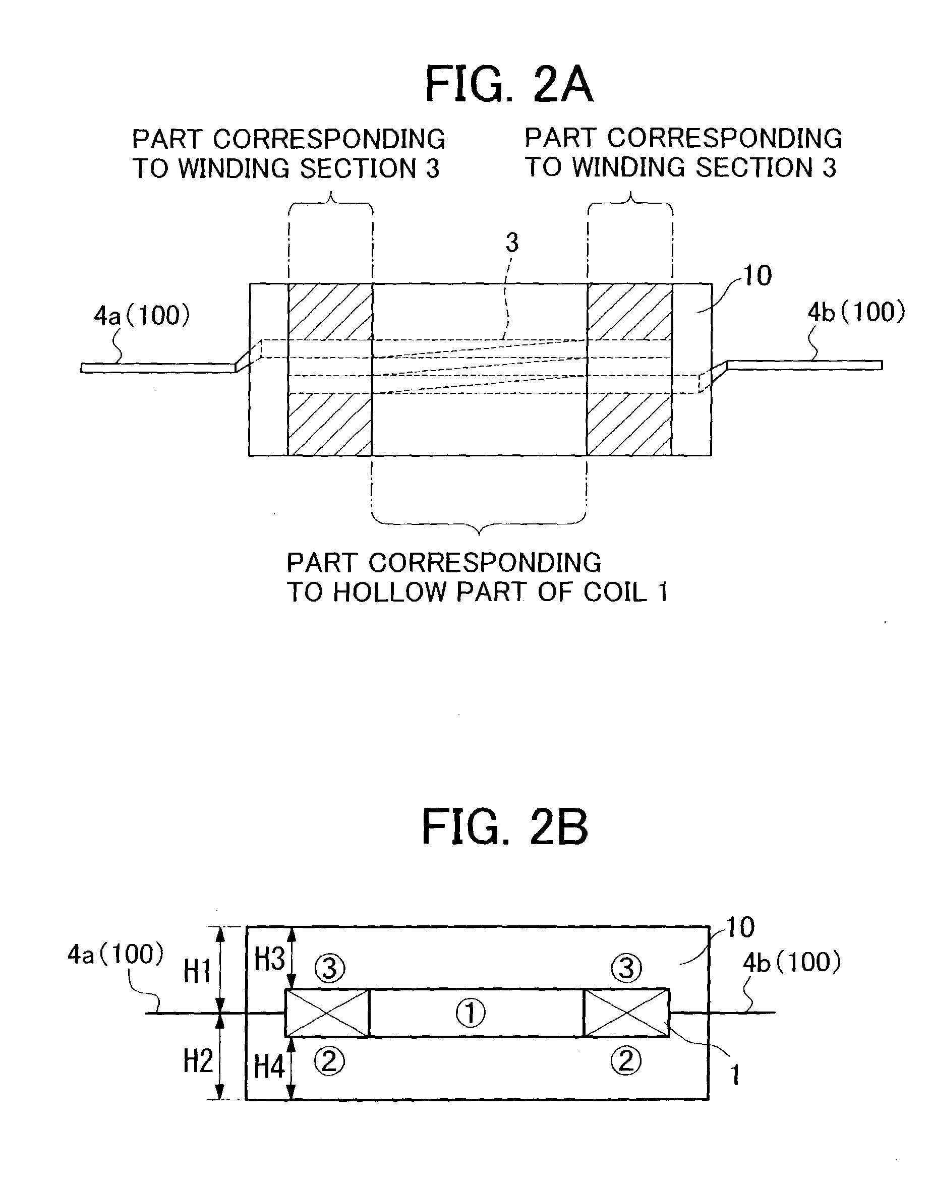
[0153] Out of the thirty samples made in the example 1, twenty samples were broken and the densities of the parts corresponding to the winding sections 3 of the coils 1 and the densities of the hollow parts of the coil 1 shown in FIG. 2A were measured using an Archimedean method with silicone oil. The result is shown in Table 1. Since the weight of each part is small, each part was taken out from twenty samples, and was measured together. The specific gravity of silicone oil is 0.817.

TABLE 1InIn airsiliconeDensity(g)oil (g)(g / cm3)Density of part8.5107.4416.50corresponding to windingsection 3 of coil 1Density of part7.2496.3276.42corresponding to hollowpart of coil 1

[0154] As shown in Table 1, the density of the part corresponding to the winding section 3 of the coil 1 shown in FIG. 2A was 6.50 g / cm3, and the density of the part corresponding to the hollow part of the coil 1 was 6.42 g / cm3. Namely, the difference between the density of the part corresponding to the winding section ...


PUM

PropertyMeasurementUnit
densityaaaaaaaaaa
wt %aaaaaaaaaa
thicknessaaaaaaaaaa

Abstract

It is an object to provide a method for manufacturing a coil-embedded dust core with a small variation in inductance value with efficiency and the like. A step (a) of charging soft magnetic metal powder including an insulating material, composing a green body 10, so as to cover a coil 1, and a step (b) of compacting the soft magnetic metal powder covering the coil 1 in an axial direction of the coil 1 are included, and in the step (b), the soft magnetic metal powder is compacted while an amount of the soft metal powder charged into the part corresponding to the winding section is kept smaller than an amount of the soft magnetic metal powder charged into the other part that are not corresponding to the winding section, with an upper surface or a lower surface of the winding section as a reference. Thereby, a coil-embedded dust core with entirely uniform density can be obtained, and according to the coil-embedded dust core with entirely uniform density, a variation in inductance value is reduced and it becomes possible to obtain a predetermined inductance value with stability.

Description

BACKGROUND OF THE INVENTION [0001] 1. Field of the Invention [0002] The present invention relates to a coil-embedded dust core, which may be used in inductors having a unitary structure with a magnetic core and in other electronic components. The present invention also relates to a method for manufacturing the coil-embedded dust core. More particularly, the invention relates to a method for manufacturing coil-embedded dust core constructed by embedding an air-core coil in a green body, and the like. [0003] 2. Description of the Related Art [0004] In recent years, electric and electronic equipment has become more compact, and dust cores that are compact (low in height) yet able to accommodate large current have come to be in demand. [0005] Materials used for dust cores are ferrite powder and ferromagnetic metal powder, but ferromagnetic metal powder has larger saturation magnetic flux density than ferrite powder and its DC bias characteristics may be maintained even in a strong magne...

Claims


Application Information

Patent Timeline
Patent Type & Authority Applications(United States)
IPC IPC(8): B22F7/08A61B8/08H01F17/04H01F41/10
CPCA61B8/08A61B8/145Y10T29/49073Y10T29/49071Y10T29/4902A61B8/4483
Inventor SATOH, SADAKITAMURA, JUNETSUMORO, HIDEHARUSUZUKI, TSUNEO
Owner TDK CORPARATION
Why Eureka
Try Eureka