Image sensor based vignetting correction

a technology of image sensor and vignetting correction, applied in the field of digital cameras, can solve the problems of undesirable use of semiconductor memory to store vignetting corrections, and achieve the effects of ensuring image resolution, allowing real-time performance, and more accurate statistics collection

Inactive Publication Date: 2005-02-10
LOGITECH EURO SA
View PDF17 Cites 16 Cited by
  • Summary
  • Abstract
  • Description
  • Claims
  • Application Information

AI Technical Summary

Benefits of technology

The invention thus allows different lens suppliers or lens types to be used in cameras as they are manufactured, by simply programming a different computed value into the register. The correction is applied on the raw sensor data after it is converted into digital form, near the sensor itself. Thus, the data is corrected prior to the optional collection of statistics on the s

Problems solved by technology

However, when this effect appears unintentionally in digital photographs, it is annoying.
In addition, the price pressure forces manu

Method used


Image

  • Image sensor based vignetting correction
  • Image sensor based vignetting correction
  • Image sensor based vignetting correction

Examples


Embodiment Construction

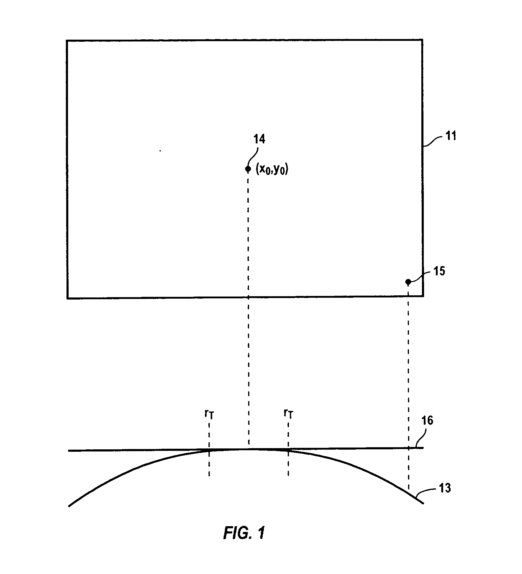
FIG. 1 illustrates a pixel array 11 and a corresponding brightness curve 13 over the Y axis. A central pixel 14 with value (x0, y0) corresponds to the point of maximum brightness of the lens. A second example pixel 15 is near the minimum brightness, showing a vignetting effect of having the difference between curve 13 and a maximum brightness value 16. The present invention corrects this vignetting effect in both X and Y directions.

In one embodiment, a threshold indicated by rT is illustrated within which the curve 13 is near the maximum value 16, and no vignetting correction need be applied. Alternately, the correction can be applied to all of the pixels regardless to avoid any transition effects at the points rT.

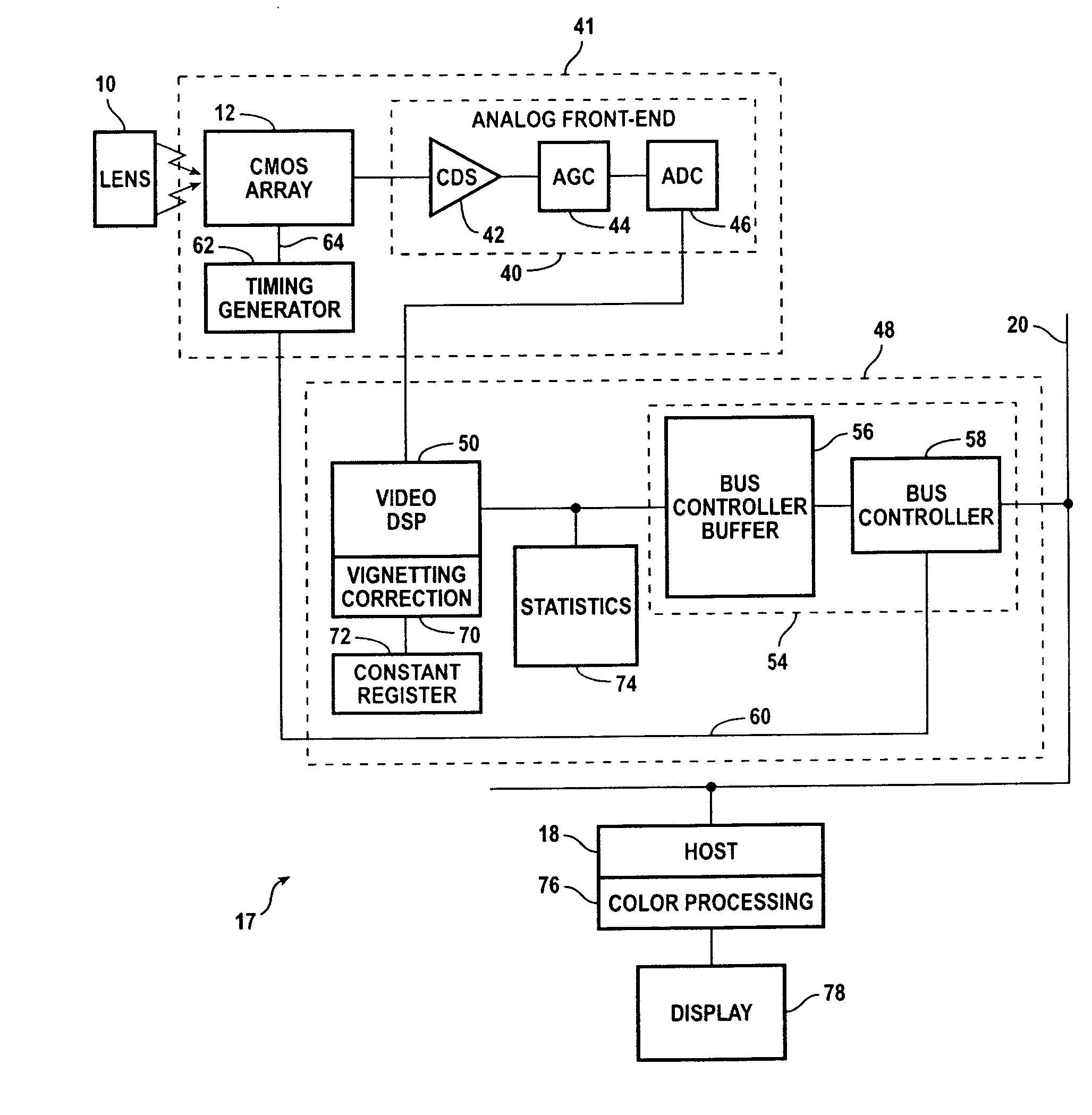
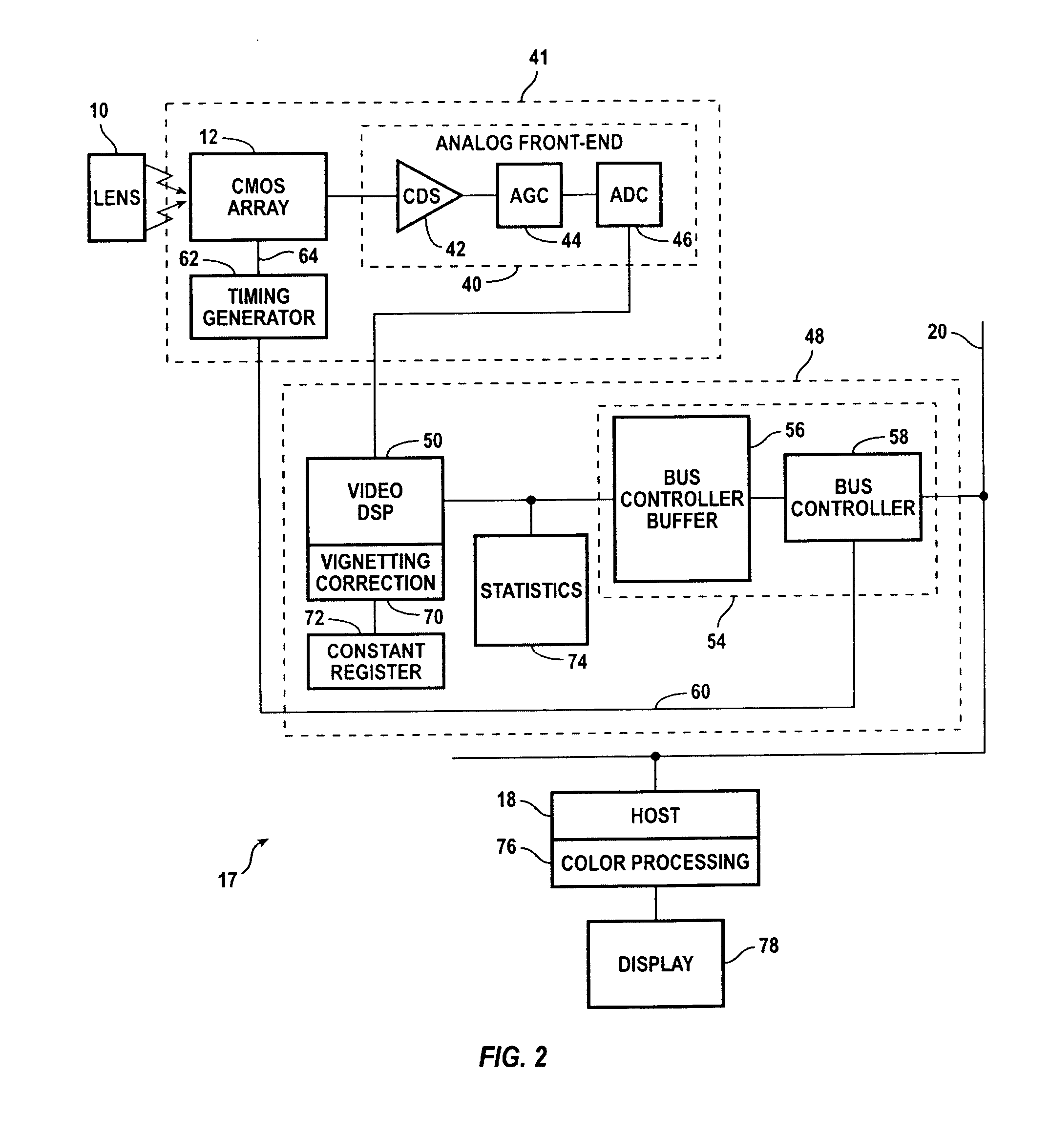
FIG. 2 illustrates a camera and computer system implementing the vignetting correction of the invention. Shown is a video camera 17 and host computer 18. Video camera 17 includes a lens 10 and a photo sensor array, such as a CMOS or CCD array 12, and is connected to a US...


PUM


Abstract

A method and apparatus for constructing an inexpensive camera with vignetting correction in the camera electronic hardware. The hardware is programmable through the use of a register storing a constant value corresponding to the amount of vignetting of a particular lens used in the camera. The register value is provided to a correction circuit which implements an algorithm that corrects for the amount of vignetting of pixels depending upon the pixel position.

Description

BACKGROUND OF THE INVENTION The present invention relates to digital cameras, and in particular to correcting vignetting effects. The vignetting effect is when the brightness around the edges of a screen is less than the brightness in the center of the screen, creating a halo effect. Professional photographers will sometimes try to intentionally create this effect with an appropriate lens or screen, to produce a softened image at the edges of a picture. However, when this effect appears unintentionally in digital photographs, it is annoying. A variety of techniques have been developed to measure and address vignetting effects. U.S. Pat. No. 4,884,140 shows an analog circuit for providing vignetting compensation for a video camera using a zoom lens which causes vignetting. U.S. Pat. No. 5,434,904 shows measuring the vignetting effect for an x-ray examination apparatus by using a constant brightness image. A correction factor is then stored in the memory for each pixel. U.S. Pat....

Claims


Application Information

Patent Timeline
IPC IPC(8): H04N5/217H04N5/232H04N5/335H04N5/357H04N7/26H04N21/4143
CPCH04N5/217H04N5/232H04N19/00H04N21/4143H04N5/3572H04N23/81H04N23/60H04N25/61
Inventor LI, WEI
Owner LOGITECH EURO SA
Why Eureka
Try Eureka