Reflective film

Inactive Publication Date: 2005-02-10
TSUJIDEN
View PDF2 Cites 67 Cited by
  • Summary
  • Abstract
  • Description
  • Claims
  • Application Information

AI Technical Summary

Benefits of technology

[0011] One of the features of the invention resides in providing a resin layer containing elastic particles on the surface, in contact with a light guiding plate, of a reflection film. Another feature of the invention resides in a reflection film containing elastic particles being therein. With a resin layer containing elastic particles provided, the elastic particles serves as a cushioning mate

Problems solved by technology

A polyolefin-based resin light guiding plate, however, has had a problem of receiving pressure damage easily because of the presence of an inorganic additive included in a depressed or protruded portion on the surface of the reflection film when constructing a backlight

Method used


Image

  • Reflective film
  • Reflective film
  • Reflective film

Examples


Example

EXAMPLES 1 TO 6

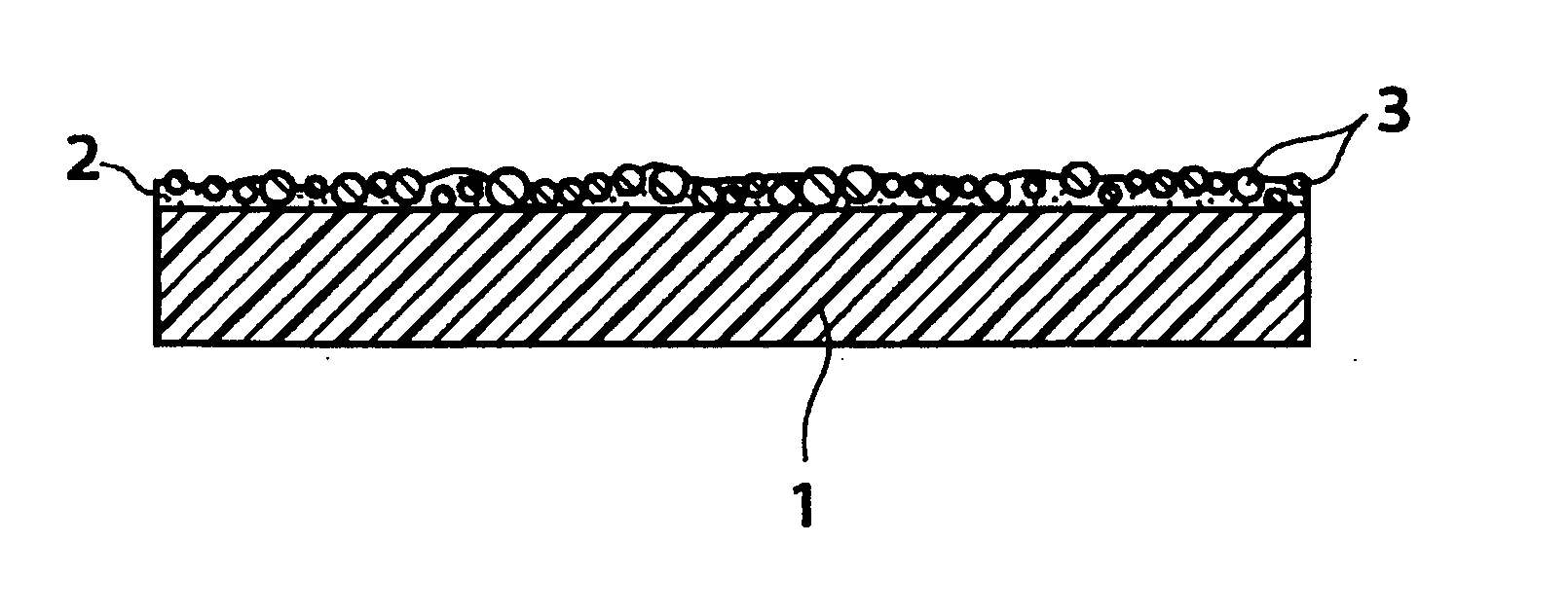
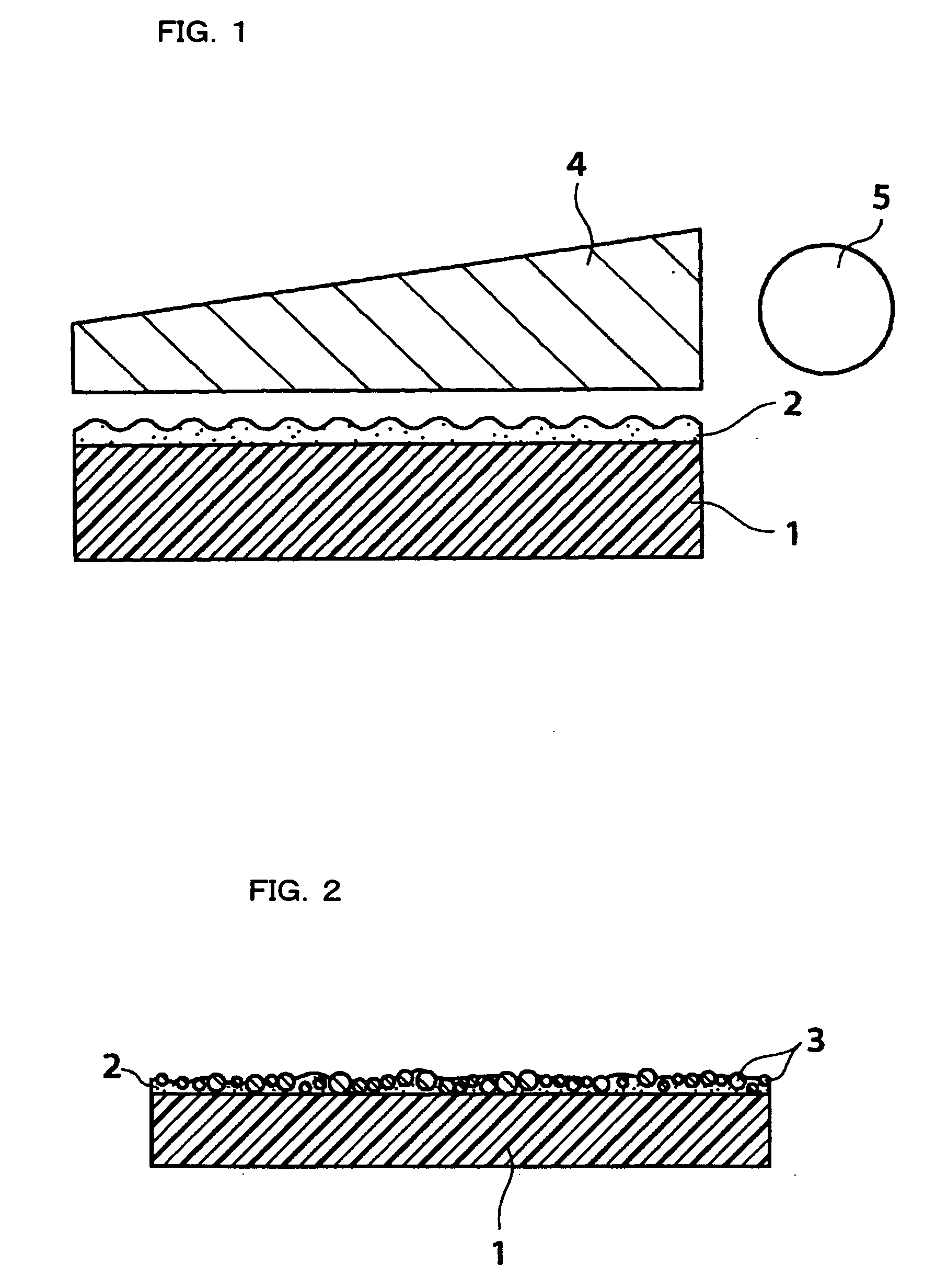
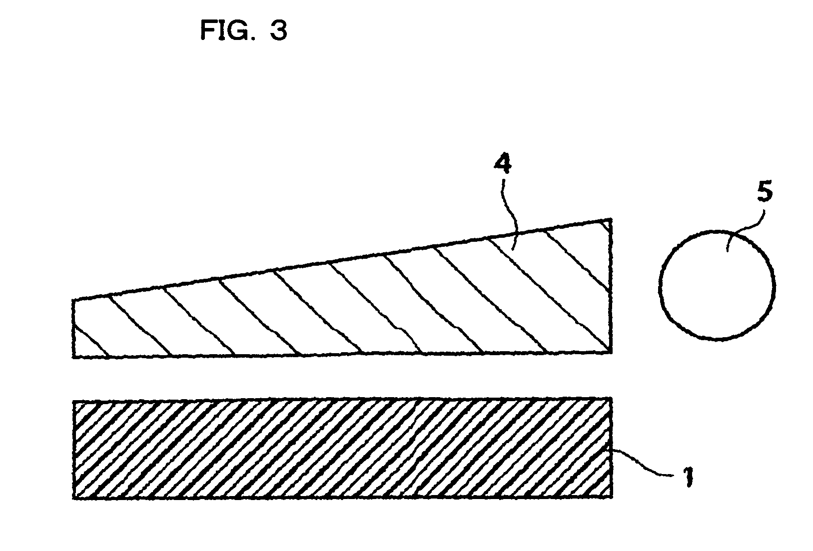
[0029] Prepared was a white polyester film (produced by TORAY INDUSTRIES, INC, with a trade name of E60L) with a thickness of 188 μm containing calcium carbonate. Then, various kinds of elastic particles (a rubber hardness of 30) shown in Table 1 were mixed in a solvent consisting of toluene, methyl ethyl ketone and butyl acetate to form a solutions. Viscosities and the like of the solution were adjusted, and the solution was applied on the reflection surface of the polyester reflection film, and the coat thereon was dried and heat treated and subjected to aging to thereby form a resin layer containing elastic particles and obtain a reflection film. Thus obtained film was cut into a piece having a proper size and was combined with the polyolefin-based light guiding plate to form a backlight optical system.

[0030] A load of 10 kg was applied on the back surface of each of the backlight optical system over an area of the order of 5 mm in diameter. After the backlight o...

Example

EXAMPLE 7

[0031] Mixed together were 100 parts by weight of acrylic-based photo-curable resin, 20 parts by weight of silicone particles (with a rubber hardness of 30) having 30 μm in average particle diameter, 5 parts by weight of a reactive diluent, 5 parts by weight of methyl ethyl ketone, 2 parts by weight of a photo initiator and 1 part by weight of a leveling agent, and the mixture was extruded through a die to form a film after transfer. Prepared were films of 50 μM and 100 μm in thickness. The films were irradiated with light and cured to obtain desired reflection films containing elastic particles. Inspection was conducted on levels of damage and light spots on the reflection films in a similar manner to that conducted in Examples 1 to 6. The level of damage on each of the light guiding plates was observed with a microscope to thereby enable a recess on the slightest scale to be recognized without any practical problem being posed, while the light spots were at a level of no...

Example

COMPARATIVE EXAMPLES 1 TO 6

[0032] A resin layers containing particles on the reflection surface of the reflection film was formed in a similar manner to that employed in Examples 1 to 6. The particles were all non-elastic. In Table 2, there are shown specifications of particles and levels of damage and levels of light spots on the light guiding plates caused by the reflection film obtained. Note that a column of added amounts of Table 2 shows part or parts by weight of elastic particles added into 100 parts by weight of a binder resin and symbols in columns of damage and light spots on the light guiding plates are evaluated at three ratings, in which a mark □ is a level at which neither damage nor a light spot is recognized on a display when a light source is turned on, a mark ∘ is a level at which a recess on the slightest scale can be recognized without any practical problem being posed and a symbol x is a problematical level at which damage or light spots can be recognized. TAB...


PUM

PropertyMeasurementUnit
Diameteraaaaaaaaaa
Diameteraaaaaaaaaa
Diameteraaaaaaaaaa

Abstract

Provided is a reflection film for a backlight optical system as a constituent of a display having a high quality by preventing damage on a light guiding plate, especially a polyolefin-based light guiding plate, with intrinsic performances of the reflection film such as an optical characteristic, a blocking property, tractability and the like sustained. A reflection film used in a backlight optical system consisting of a light source, a light guiding plate and a reflection film, wherein a resin layer containing particles with elasticity is provided on a surface, in contact with the light guiding plate, of the reflection film. The reflection film contains particles with elasticity therein. It is preferable that the particles with elasticity each have a cushioning property and elasticity and a rubber hardness (JIS K6253) of 50 or less. Specifically, the particles with elasticity each are preferably made of silicone, crosslinked polyacrylate ester, polyurethane or the like. The diameters of the particles with elasticity are preferably in the range of from 1 to 60 μm.

Description

TECHNICAL FIELD [0001] The invention relates to a reflection film. More particularly, the invention relates to a reflection film with high homogeneity used in a backlight optical system for a liquid crystal display. BACKGROUND ART [0002] A liquid crystal display is rapidly enlarging its application fields as a display means for IT-related equipments such as a computer, a television set, a mobile, communication equipment and the like. Especially, reduction in weight, downsizing, an improved display quality and such have been strongly requested in a notebook personal computer, a portable telephone, a mobile and the like from the viewpoint of portability and convenience. Along with such a trend, reduction in weight, downsizing and, in addition, toughness have also been increasingly desired in a backlight unit, which is a component of such IT-equipment. [0003] A sidelight type backlight unit is basically, as shown in FIG. 3, an optical system consisting of a light source 5, a light guid...

Claims


Application Information

Patent Timeline
IPC IPC(8): C08J7/043C08J7/046F21V8/00G02B1/10G02B5/08
CPCC08J7/045C08J7/047C08J7/123C08J2323/00G02B6/0055C08J2433/00C08J2483/00G02B5/08G02B5/0808C08J2367/00C08J7/0423C08J7/0427C08J7/043C08J7/046
Inventor OHNISHI, ARATAKAOGAWA, SATOSHI
Owner TSUJIDEN
Why Eureka
Try Eureka