

Shake correcting device, shake correcting method and control program for implementing the method
- Summary
- Abstract
- Description
- Claims
- Application Information
AI Technical Summary
Benefits of technology
Problems solved by technology
Method used
Image

Examples
first embodiment
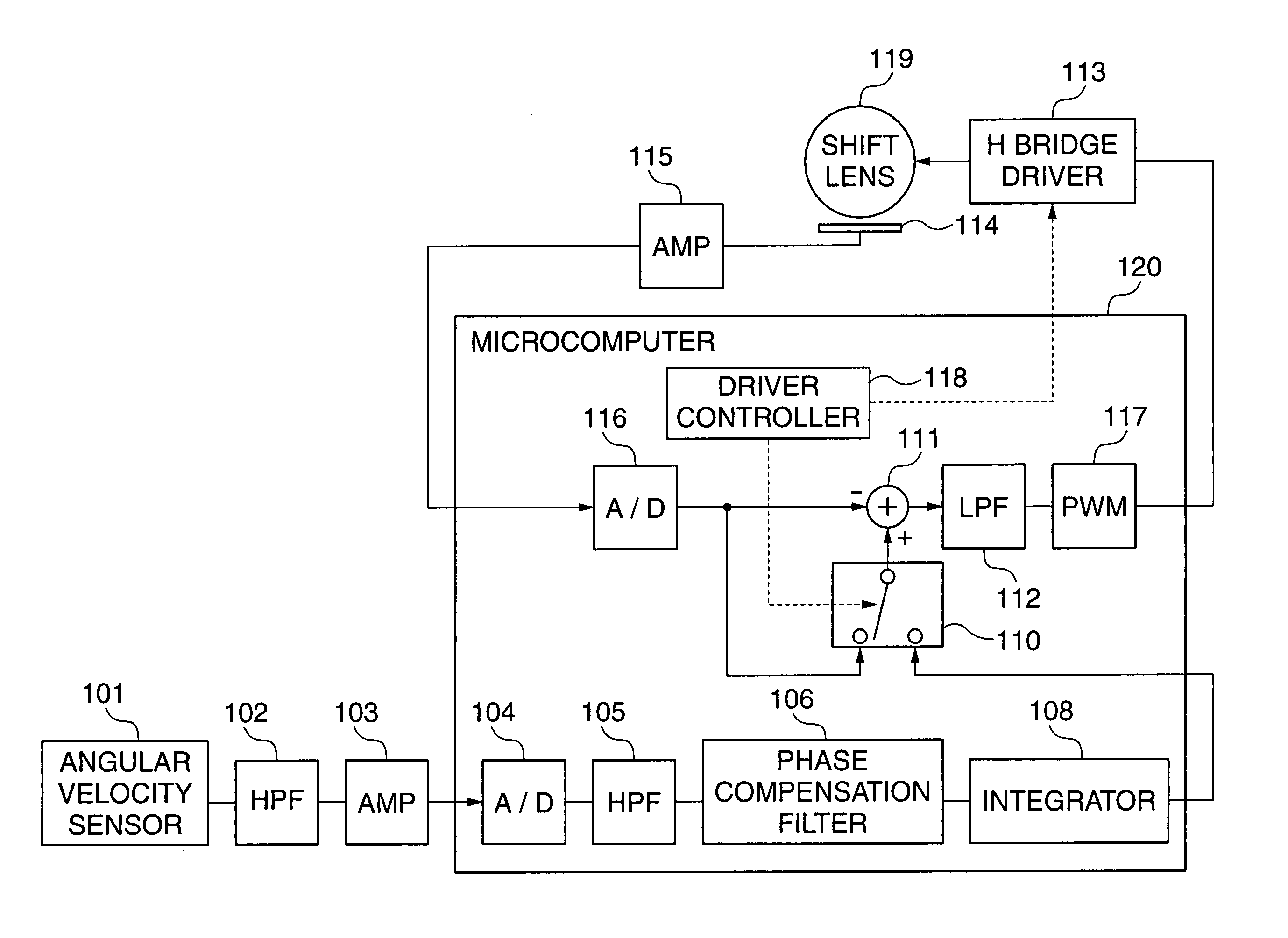
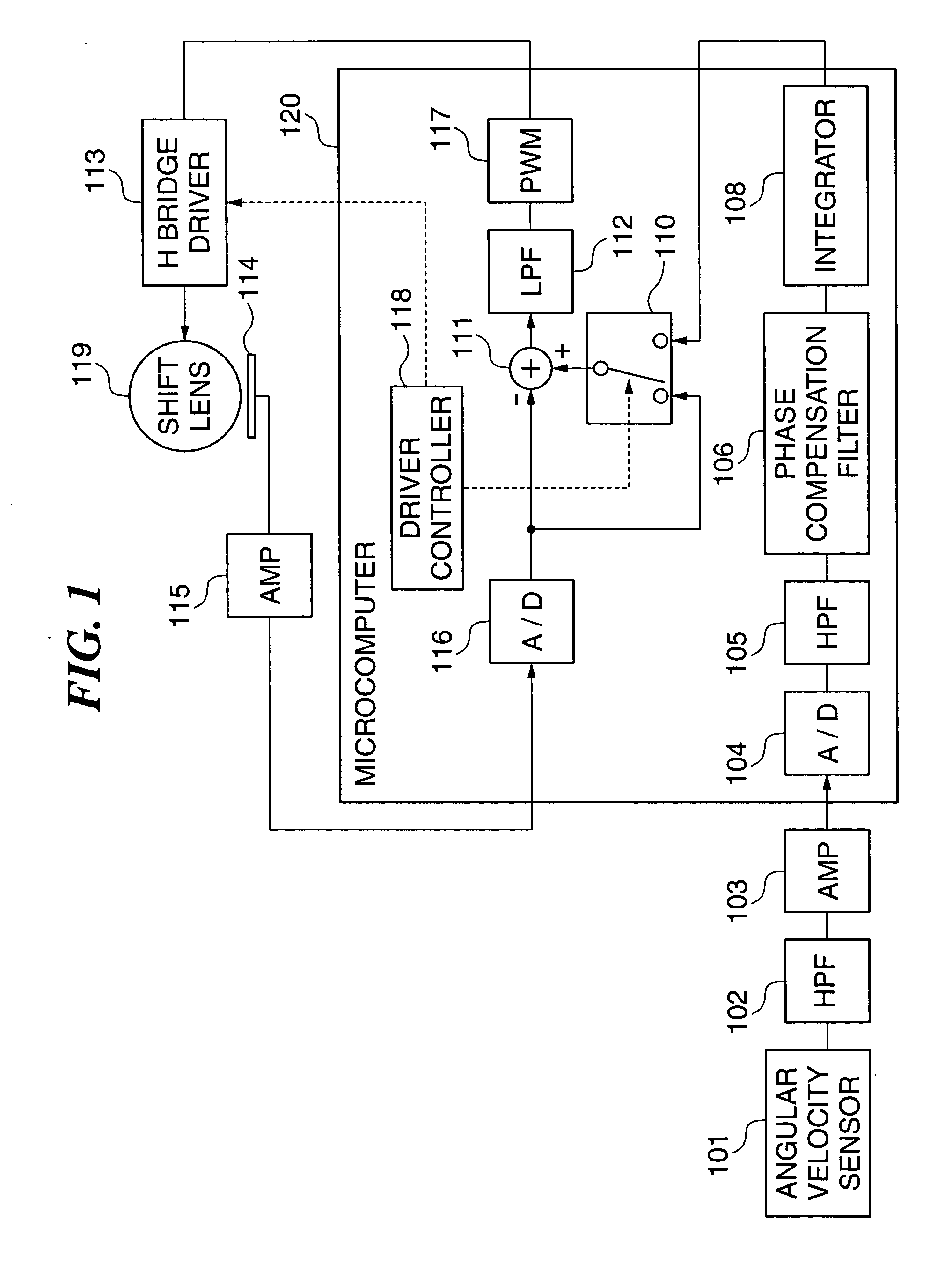
[0050]FIG. 1 is a block diagram schematically showing the arrangement of a shake correcting device according to the present invention. The shake correcting device shown in FIG. 1 basically has the same arrangement as that of the shake correcting device shown in FIG. 9. Therefore, component parts and elements corresponding to those shown in FIG. 9 are designated by identical reference numerals, and detailed description thereof is omitted. Shake correction is typically carried out biaxially in lateral and longitudinal directions, but in the present embodiment, a description will be given of only shake correction carried out along a single axis, for simplicity. Further, in a microcomputer appearing in FIG. 1, there are illustrated only sections related to the control of shake correction.
[0051] The arrangement of the shake correcting device of the present embodiment is distinguished from the conventional shake correcting device shown in FIG. 9 in that the microcomputer 120 additionally ...
second embodiment
[0067]FIG. 4 is a block diagram schematically showing the arrangement of a shake correcting device according to the present invention. The shake correcting device shown in FIG. 4 basically has the same arrangement as that of the shake correcting device shown in FIG. 1. Therefore, component parts and elements corresponding to those shown in FIG. 1 are designated by identical reference numerals, and detailed description thereof is omitted.
[0068] The arrangement of the shake correcting device according to the present embodiment is distinguished from that of the shake correcting device shown in FIG. 1 in that in the microcomputer 120, the integrator 108 is replaced by an integrator 401 as a characterizing feature of the present embodiment; the output selection switch 110 is omitted; and a switching signal from the driver controller 118 and an output signal from the A / D converter 116 as data indicative of the output from the position sensor 114, are additionally supplied to the integrato...
PUM
 Abstract
Description
Claims
Application Information