
Reduction method of catalysts using non-thermal plasma

Inactive Publication Date: 2005-02-10
KOREA INST OF SCI & TECH
View PDF7 Cites 11 Cited by
  • Summary
  • Abstract
  • Description
  • Claims
  • Application Information

AI Technical Summary

Benefits of technology

[0011] An object of the invention is to provide a reduction method of catalysts using non-thermal plasma which is economical and efficient because there is no need for a separate heating device to make a high temperature condition and it is possible to shorten the reaction time for reduction by using non-thermal plasma for catalyst reduction instead of using conventional heating methods.
[0012] Another object of the invention is to provide a method of catalysts reduction using non-thermal plasma which allows a continuity between catalysts reductions and the reactions using the reduced catalysts, since the same reactor used for catalyst reduction using non-thermal plasma is used as it is.

Problems solved by technology

However, the method of reduction at this high temperature has problems for reduction when the reactor used for chemical reactions has a structure difficult for heating or is disposed unsuitable for additional heating.

Method used


Image

  • Reduction method of catalysts using non-thermal plasma
  • Reduction method of catalysts using non-thermal plasma
  • Reduction method of catalysts using non-thermal plasma

Examples


embodiment 1

[0039] 1 wt % Pt / γ(gamma)-Al2O3 catalyst was produced by an incipient wetness method using carriers of alumina and precursor of H2PtCl6.6H2O. Then 1 g of the catalyst was filled into the bottom of a cylinder-wire type dielectric barrier discharge reactor having an interior volume of 10 cc. Then, while hydrogen and nitrogen mixed by volume ratio of 1:4 was being flowed into the dielectric barrier discharge reactor, non-thermal plasma was generated. Reduction reactions progress as hydrogen molecules activated by plasma combine with oxygen atoms on the surface of metal oxide catalysts carried by alumina to form water.

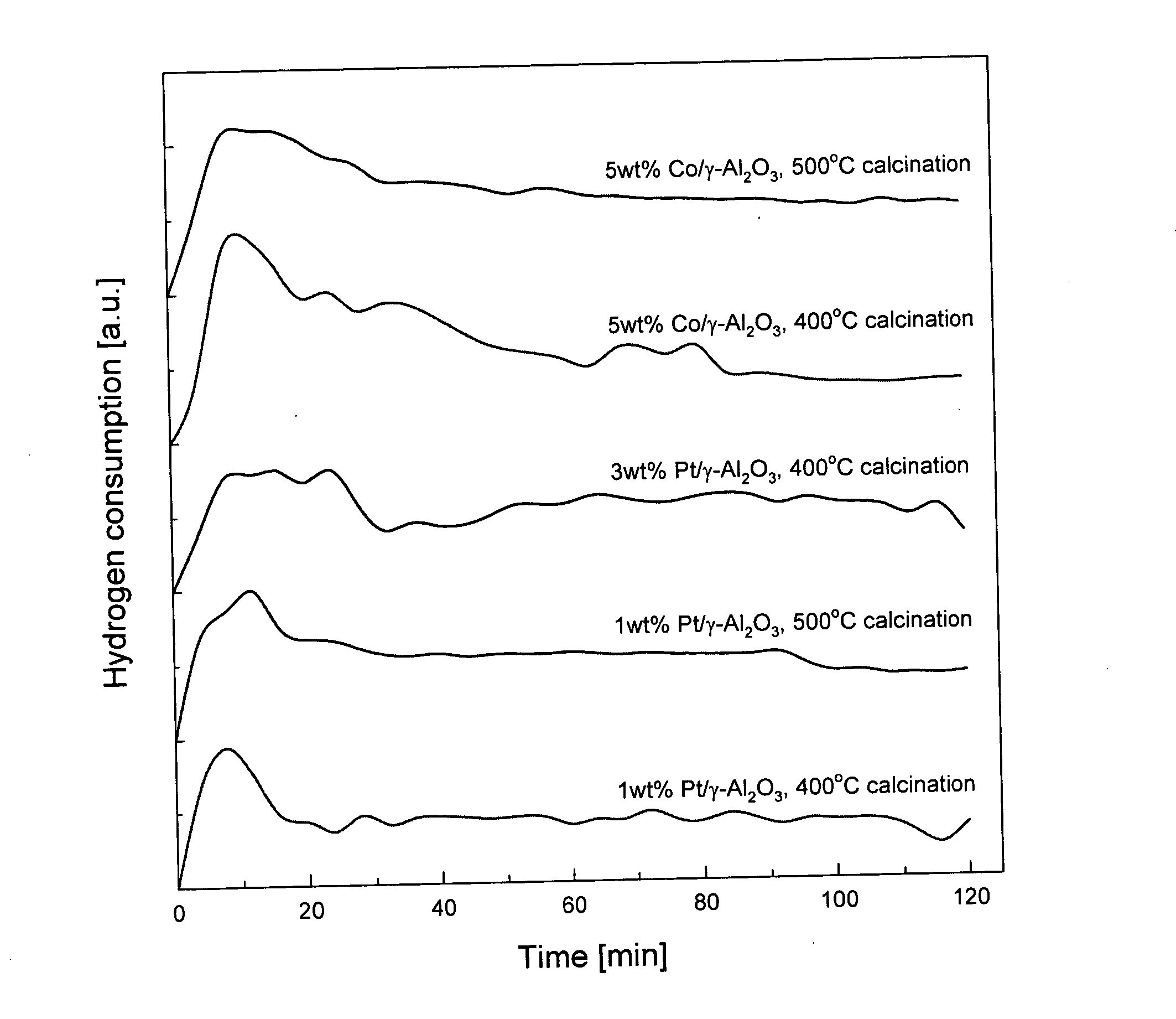
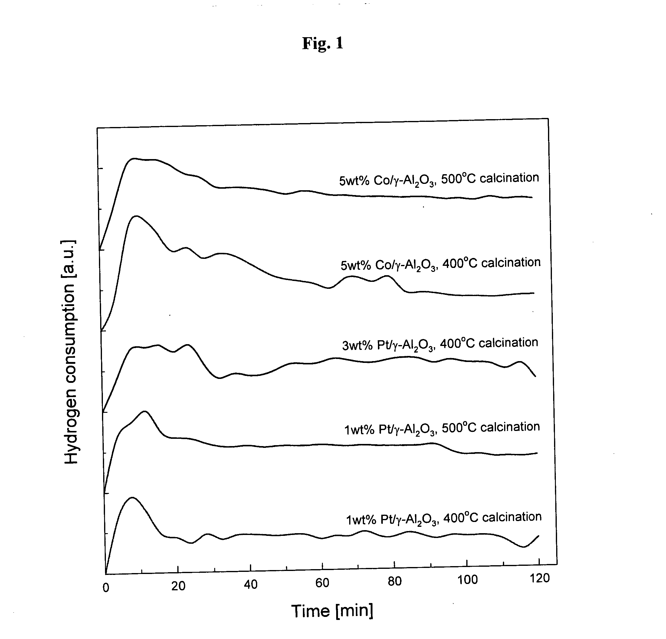
[0040]FIG. 1 shows the amount of hydrogen consumptions as time elapses when metal (such as platinum and cobalt) catalysts are reduced using non-thermal plasma in accordance with the present invention. As shown in FIG. 1, hydrogen is consumed rapidly at the initial stage of reactions and the reduction of platinum catalysts is almost complete within 40 minutes.

[0041] To ch...

embodiment 2

[0048] 5 wt % Co / γ-Al2O3 catalyst was produced by an incipient wetness method using carriers of alumina and precursor of Co(NO3)2.6H2O. Then 1 g of the catalyst was filled into the bottom of a cylinder-wire type dielectric barrier discharge reactor having an interior volume of 10 cc. Then, while hydrogen and nitrogen mixed by volume ratio of 1:4 were being flowed into the dielectric barrier discharge reactor, non-thermal plasma was generated. Reduction reactions progress as hydrogen molecules activated by plasma combine with oxygen atoms on the surface of metal oxide catalysts carried by alumina to form water.

[0049]FIG. 1 shows the amount of hydrogen consumptions as time elapses when metal (such as platinum and cobalt) catalysts are reduced using non-thermal plasma in accordance with the present invention. As shown in FIG. 1, hydrogen is consumed rapidly at the initial stage of reactions and the reduction of platinum catalysts is almost complete within 60 minutes.

[0050] To check t...


PUM

PropertyMeasurementUnit
Fractionaaaaaaaaaa
Fractionaaaaaaaaaa
Fractionaaaaaaaaaa

Abstract

A method of catalysts reduction using non-thermal plasma according to the present invention is characterized to reduce catalysts containing metal compounds by bringing them into contact with hydrogen-containing gas under a non-thermal plasma state. In the method of catalysts reduction using non-thermal plasma according to the present invention, said non-thermal plasma is generated by dielectric barrier discharge. In the method of catalysts reduction using non-thermal plasma according to the present invention, the plasma energy that is required to vary depending on the types of metals is regulated by the magnitude of power via voltage regulation. In the method of catalysts reduction using non-thermal plasma according to the present invention, said reduction method is conducted in conjunction with existing methods of gaseous hydrogen reduction by heating, electrochemical reduction methods, or methods of reduction by adding organic or inorganic reducing agents.

Description

BACKGROUND OF THE INVENTION [0001] 1. Field of the Invention [0002] The present invention relates to a method of reducing metal catalysts, more particularly to an economical and efficient method of reducing catalysts using non-thermal plasma instead of using conventional heating methods so that no separate heating device to make a high temperature condition is required and the time for reduction reactions is shortened. [0003] 2. Description of the Related Art [0004] Most catalysts used in chemical reactions in current use are metal catalysts coated on catalysts carriers. These metal catalysts are produced first by dissolving precursors that are metal salts in a solvent and then coating this solution on non-metallic carriers in various ways. These catalysts undergo an oxidation process by heating at a high temperature in an oxygen atmosphere to eliminate the salt components contained in the precursors and then obtain pure metals. The catalysts undergone this oxidation process has a f...

Claims


Application Information

Patent Timeline
IPC IPC(8): B01J38/10B01J23/42B01J23/75B01J37/18B01J37/34
CPCB01J23/42B01J37/349B01J37/18B01J23/75B01J38/10
Inventor SONG, HYUNG KEUNLEE, HWAUNGCHOI, JAE-WOOKYANG, GI-SEOKKIM, SEUNG-SOONA, BYUNG-KI
Owner KOREA INST OF SCI & TECH
Learn More