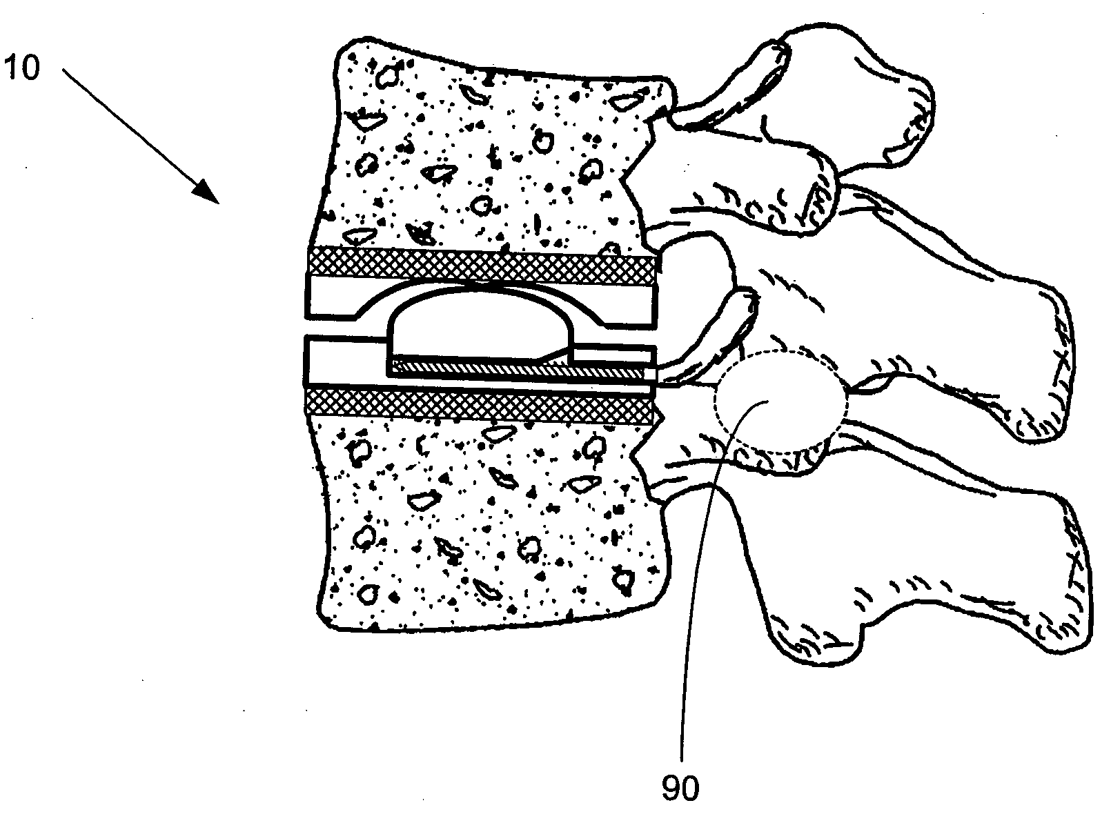
[0017] Since a properly functioning natural FSU relies on intact posterior elements (facet joints) and since it is necessary to remove these elements to place a posterior interbody device, a two-step procedure is disclosed that allows for placement of an expandable intervertebral
implant and replacement of one or both facets that are necessarily removed during the surgical procedure. The expansile nature of the disclosed devices allow for restoration of
disc height once inside the vertebral interspace. The expandable devices are collapsed prior to placement and then expanded once properly inserted in the
intervertebral space. During the process of expansion, the endplates of the natural
intervertebral disc, which essentially remain intact after removal or partial removal of the remaining natural disc elements, are compressed against the device, which thereby facilitates bony end growth onto the surface of the artificial implant. Once the interbody device is in place and expanded, the posterior element is reconstructed with the disclosed
pedicle screw and rod
system, which can also be used to distract the
disk space while inserting the artificial implant. Once the interbody device is in place and expanded, the posterior element is further compressed, again promoting bony end growth into the artificial implant. This posterior compression allows for anterior flexion but replaces the limiting element of the facet and interspinous
ligament and thereby limits flexion to some degree, and in doing so maintains stability for the anteriorly located interbody device.
[0018] The
posterior approach avoids the potential risks and morbidity of the
anterior approach, which requires mobilization of the vascular structures, the
ureter, and exposes the bowels to risk. Also, the
anterior approach does not offer the surgeon an opportunity to view the posterior neural elements and thereby does not afford an opportunity for decompression of those elements. Once an anterior
exposure had been utilized a revision procedure is quite risky and carries significant morbidity.
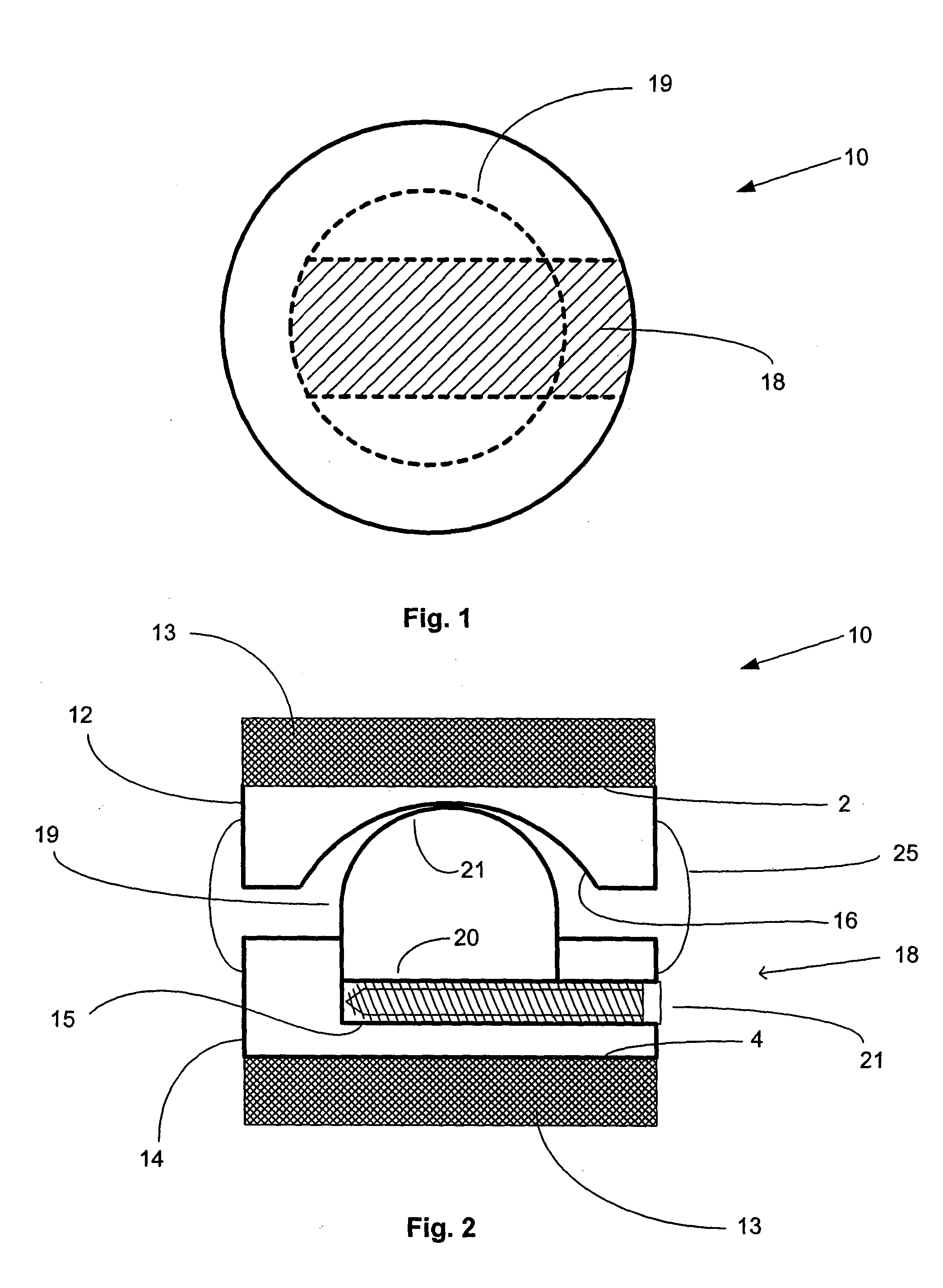
[0019] The artificial FSU generally comprises an expandable intervertebral implant and one or more artificial facet joints. The expandable intervertebral implant generally comprises a pair of spaced apart plate members, each with a
vertebral body contact surface. The general shape of the plate members may be round, square, rectangular, banana shaped,
kidney shaped, or some other similar shape, depending on the desired vertebral
implantation site. Because the artificial intervertebral implant is to be positioned between the facing surfaces of adjacent vertebral bodies, the plate members are arranged in a substantially parallel planar alignment (or slightly offset relative to one another in accordance with proper lordotic angulation) with the
vertebral body contact surfaces facing away from one another. The plate members are to mate with the vertebral bodies so as to not rotate relative thereto, but rather to permit the spinal segments to axially compress and bend relative to one another in manners that mimic the natural motion of the
spinal segment. This natural motion is permitted by the performance of an expandable joint insert, which is disposed between the plate members. The securing of the plate members to the
vertebral bone is achieved through the use of a osteoconductive scaffolding machined into the exterior surface of each plate member. Alternatively, a mesh of osteoconductive surface may be secured to the exterior surface of the plate members by methods known in the art. The osteoconductive scaffolding provides a surface through which bone may ultimately grow. If an osteoconductive mesh is employed, it may be constructed of any
biocompatible material, both
metal and non-
metal. Each plate member may also comprise a
porous coating (which may be a sprayed deposition layer, or an
adhesive applied beaded
metal layer, or other suitable porous coatings known in the art, i.e. hydroxy
appetite). The
porous coating permits the long-term ingrowth of
vertebral bone into the plate member, thus permanently securing the
prosthesis within the
intervertebral space.
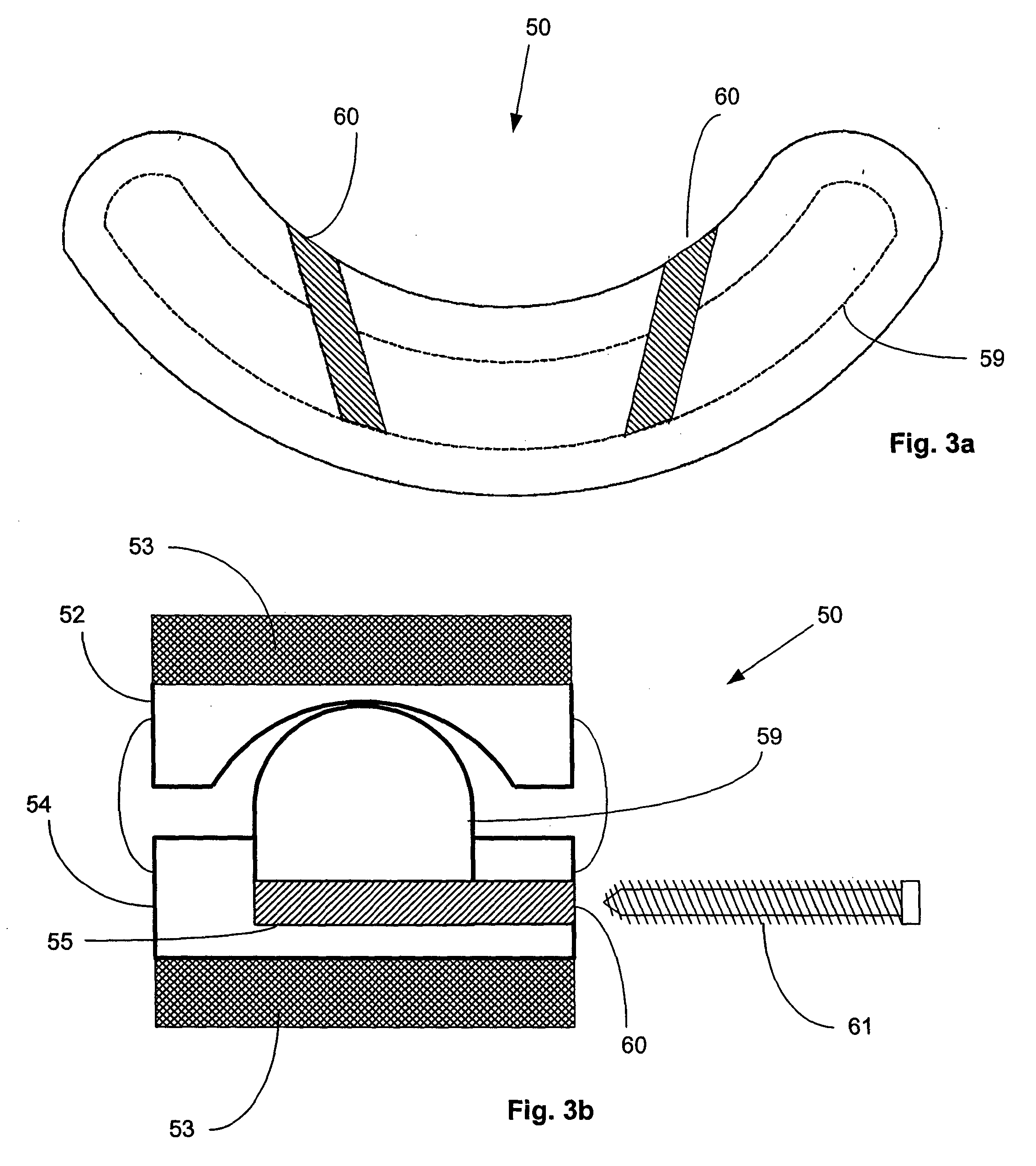
[0022] In addition, another embodiment of the artificial
facet joint is disclosed that generally comprises two locked pedicle screws joined by a rod having a
ball and socket joint centrally located on the rod between the two pedicle screws. The locking of the pedicle screws prevents the
screw head from swiveling, but allows rotation and translation of the rod.
[0023] In instances where a fusion procedure is unavoidable, a PLIF and TLIF cage are disclosed that utilize the expansion principal of the functional artificial intervertebral implant. The cage generally comprises three parts: An external body, an internal body, and an expansion device. The external and internal bodies will have substantially the same shape and will be shaped accordingly to the procedures for which they will be used, more specifically, a rectangular cage is employed for a PLIF procedure and round or banana shaped cage is employed for the TLIF procedure. Both the external and internal bodies comprise a mesh structure in which an osteoconductive substance can be placed (i.e. morsilized autograph or an osteobiologic substitute). The external body of the cage contains an internal
void space that houses the internal body. The external body further comprises an expansion window on its superior surface through which the internal body is raised upon expansion of the cage. The internal body comprises a planar plate member that is slightly larger than the expansion window in the superior surface of the external body such that when the cage is expanded the planar plate member secures itself against the interior side of the expansion window, thereby
interlocking the external and internal bodies and eliminating mobility between the two bodies. Similar to the functional expandable implant, an expansion device is placed through an expansion slot. The expansion device lifts the internal body relative to the external body,
interlocking the planar plate member of the internal body against the interior of the expansion window, and pushing the mesh structure of the internal body through the expansion window and above the superior surface of the external body. Varying the height of the expansion device and the dimensions of the external and internal bodies allows for various
distraction heights to regain
disc space. As with the functional intervertebral implant, the PLIF and TLIF cages may take the form of either an expandable lordotic cage or a non-lordotic cage.

