Jet aircraft electrical energy production system

a technology for electrical energy production and jet aircraft, applied in the field of aircraft power plants, can solve the problems of limited use of batteries and fuel driven electric generators, and achieve the effect of increasing the efficiency of the combustion phas

Inactive Publication Date: 2005-02-17
GONZALEZ E H
View PDF17 Cites 33 Cited by
  • Summary
  • Abstract
  • Description
  • Claims
  • Application Information

AI Technical Summary

Benefits of technology

[0021] The jet aircraft electrical energy production system of the present invention produces electric energy and increases the efficiency of the combustion phase of a jet engine through both the thermal and mechanical excitation of fluid ions.

Problems solved by technology

Supplying electric energy onboard an airplane in flight provides challenges unlike those encountered elsewhere.
Weight concerns and fuel supply have limited the use of batteries and fuel driven electric generators.

Method used


Image

  • Jet aircraft electrical energy production system
  • Jet aircraft electrical energy production system
  • Jet aircraft electrical energy production system

Examples


Embodiment Construction

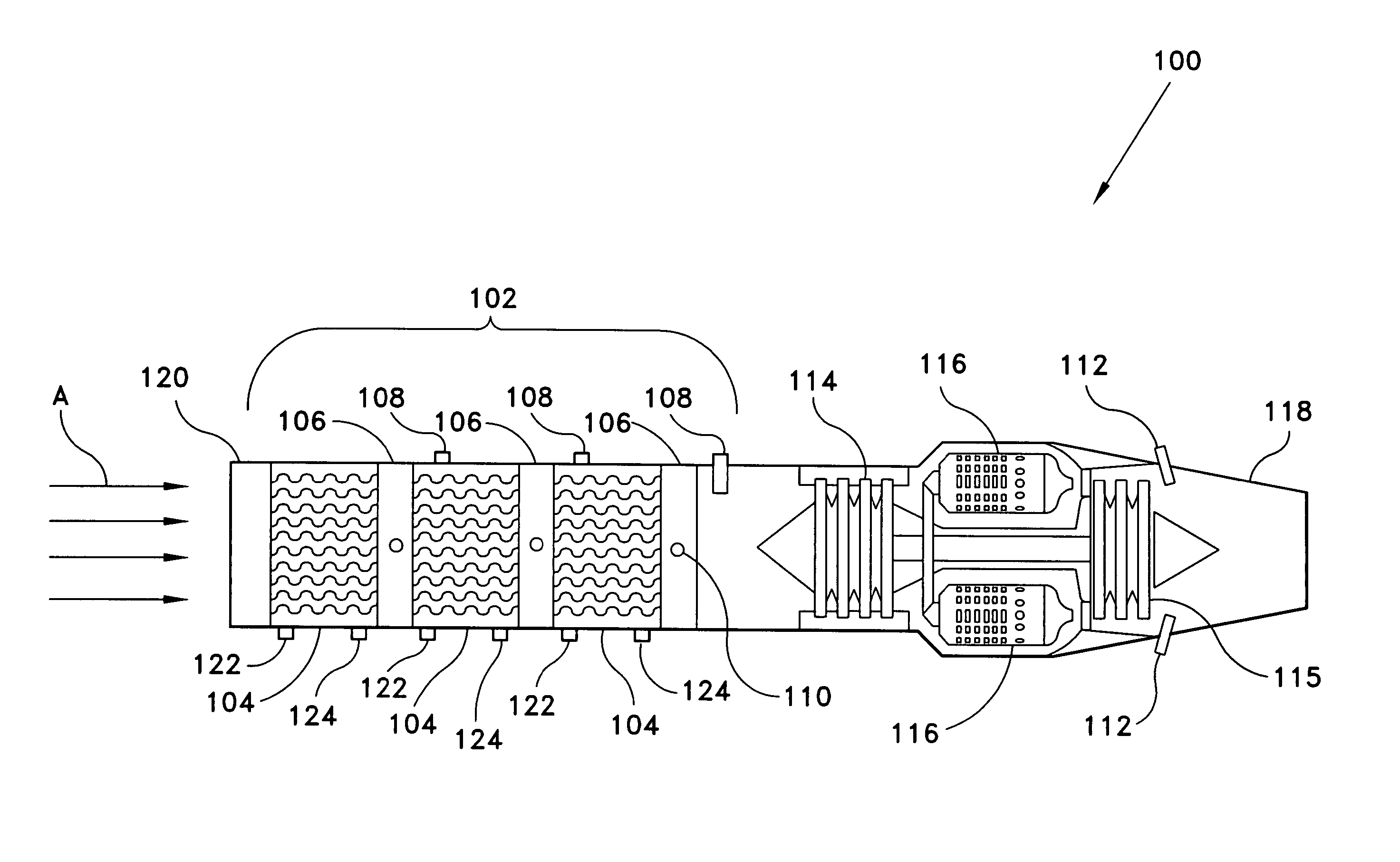
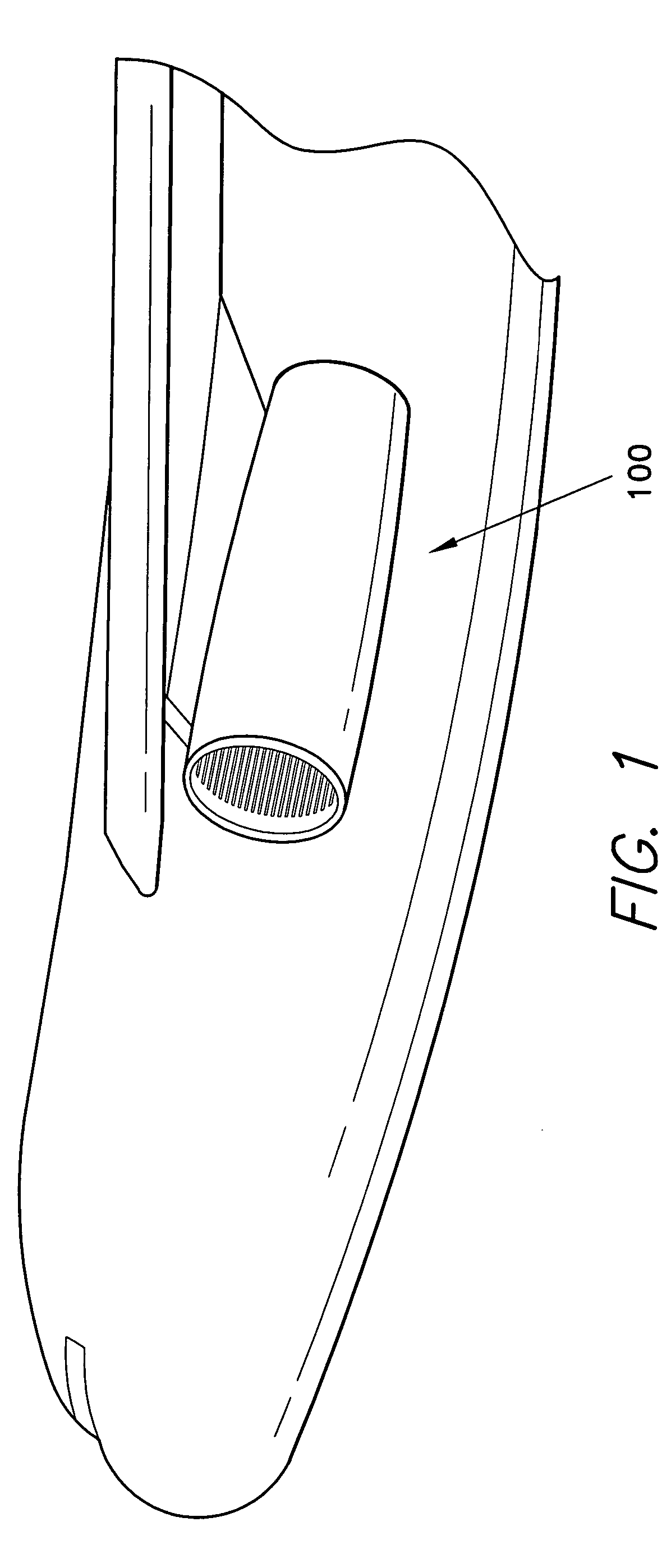
[0041] The present invention is directed to an electrical energy production system for jet aircraft, designated generally as 100 in the drawings. Integrated into the axial flow of a jet aircraft engine, as shown in FIG. 1, the present invention has the added functionality of increasing the output thrust of a jet engine using the ionization of air molecules to provide a more reactive component of combustion thereby increasing the output thrust output of a ram jet or turbojet engine.

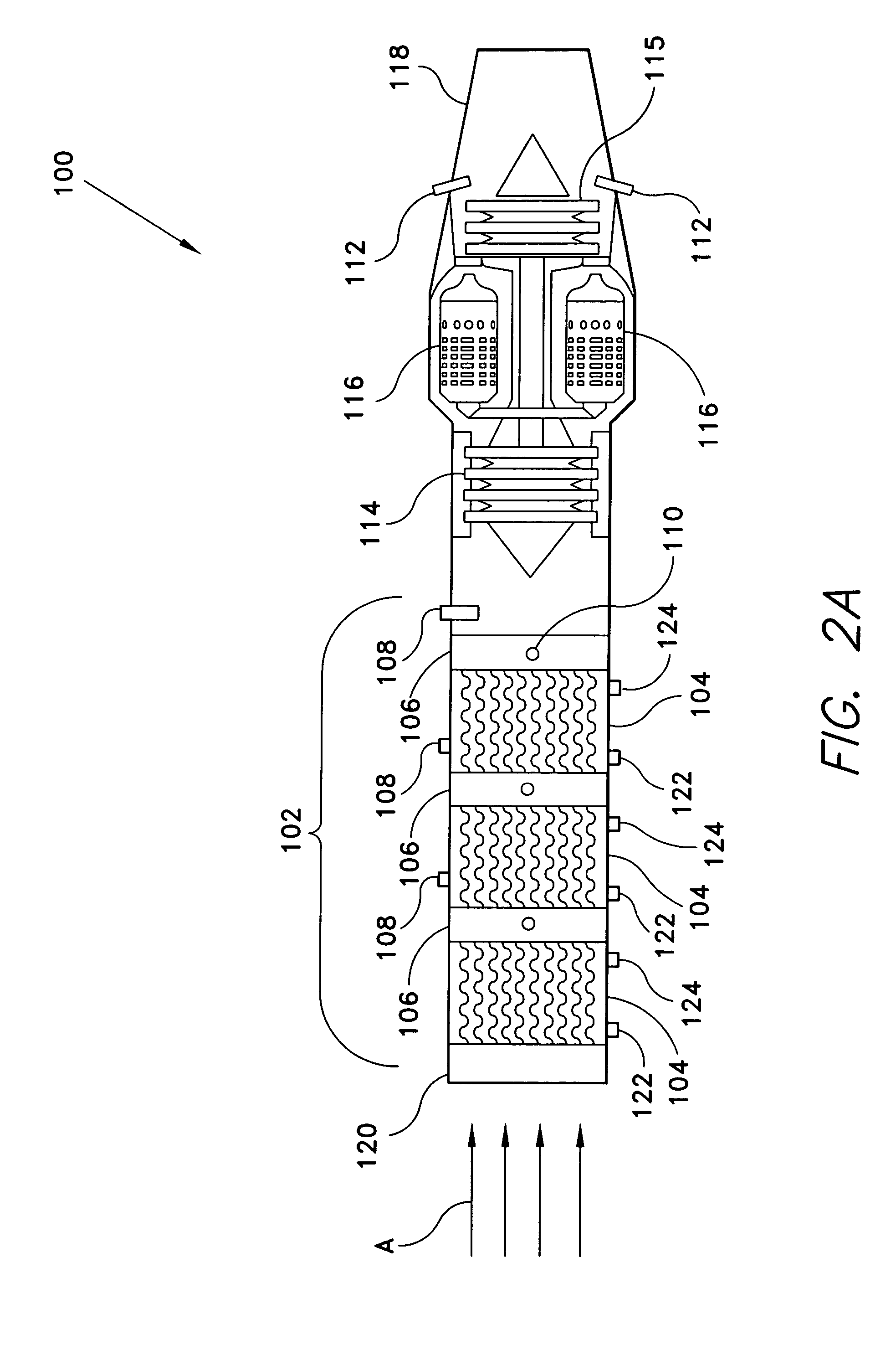
[0042] The system 100 is preferentially embodied as modifications to jet engines, as shown in FIGS. 2A, 2B, and 3. The gas ionization and energy production section 102 is similar to the apparatus disclosed in the inventor's prior U.S. Pat. No. 6,486,483, hereby incorporated by reference in its entirety. The gas ionization and electric energy production section 102 generates electricity by forcing large volumes of ambient air A through a series of separate tubular sections butted together, and may be joine...


PUM


Abstract

The jet aircraft electrical energy production system produces electrical energy by ionizing airflow through a ram or gas turbine jet engine. The ionized particles in the airflow may also be separated, liquefied, stored for future utilization.

Description

BACKGROUND OF THE INVENTION [0001] 1. Field of the Invention [0002] The present invention relates to aircraft power plants in general, and more particularly, to systems for producing electrical energy and liquefaction of air through fluid ionization. [0003] 2. Description of the Related Art [0004] Improvement in the generation of electric energy is an ongoing goal of research scientists. Improving the capability of electricity production onboard an aircraft in flight is another area that has seen much research and development. [0005] As disclosed in U.S. Pat. No. 6,486,483, issued to the present inventor, E. H. Gonzalez, on Nov. 26, 2002 and incorporated in its entirety in the current patent application, some of the most significant advances in the field of electric energy production have centered on thermal exciter units for forming plasma, which can then be used to generate electricity. [0006] U.S. Pat. No. 3,119,233, issued to F. L. Wattendorf et al. in 1964, shows a multiple ele...

Claims


Application Information

Patent Timeline
Patent Type & Authority Applications(United States)
IPC IPC(8): F02C3/20F02C7/32F02K7/10F02K7/16F03H1/00H02N3/00
CPCF02C3/20F02C7/32F02K7/10H02N3/00F03H1/00F23L2900/00001F02K7/16
Inventor GONZALEZ, E. H.
Owner GONZALEZ E H
Why Eureka
Try Eureka