Heat exchanger optimization process and apparatus

a technology of heat exchanger and heat exchanger, which is applied in the direction of heating apparatus, application, gas/liquid distribution and storage, etc., can solve the problems of greater pressure loss of natural gas, achieve maximum net power (and thereby energy) savings, reduce the amount of energy, and increase the transmission efficiency of the gas pipeline system

Inactive Publication Date: 2005-02-17
VARNEY BRIAN WILSON
View PDF2 Cites 45 Cited by
  • Summary
  • Abstract
  • Description
  • Claims
  • Application Information

AI Technical Summary

Benefits of technology

An increase in gas flow rate through a heat exchanger results in greater heat transfer (i.e. greater cooling of the total gas flow coming from the upstream compressor), and vice versa. However an increase in gas flow rate also results in a greater pressure loss for the natural gas, and vice versa.
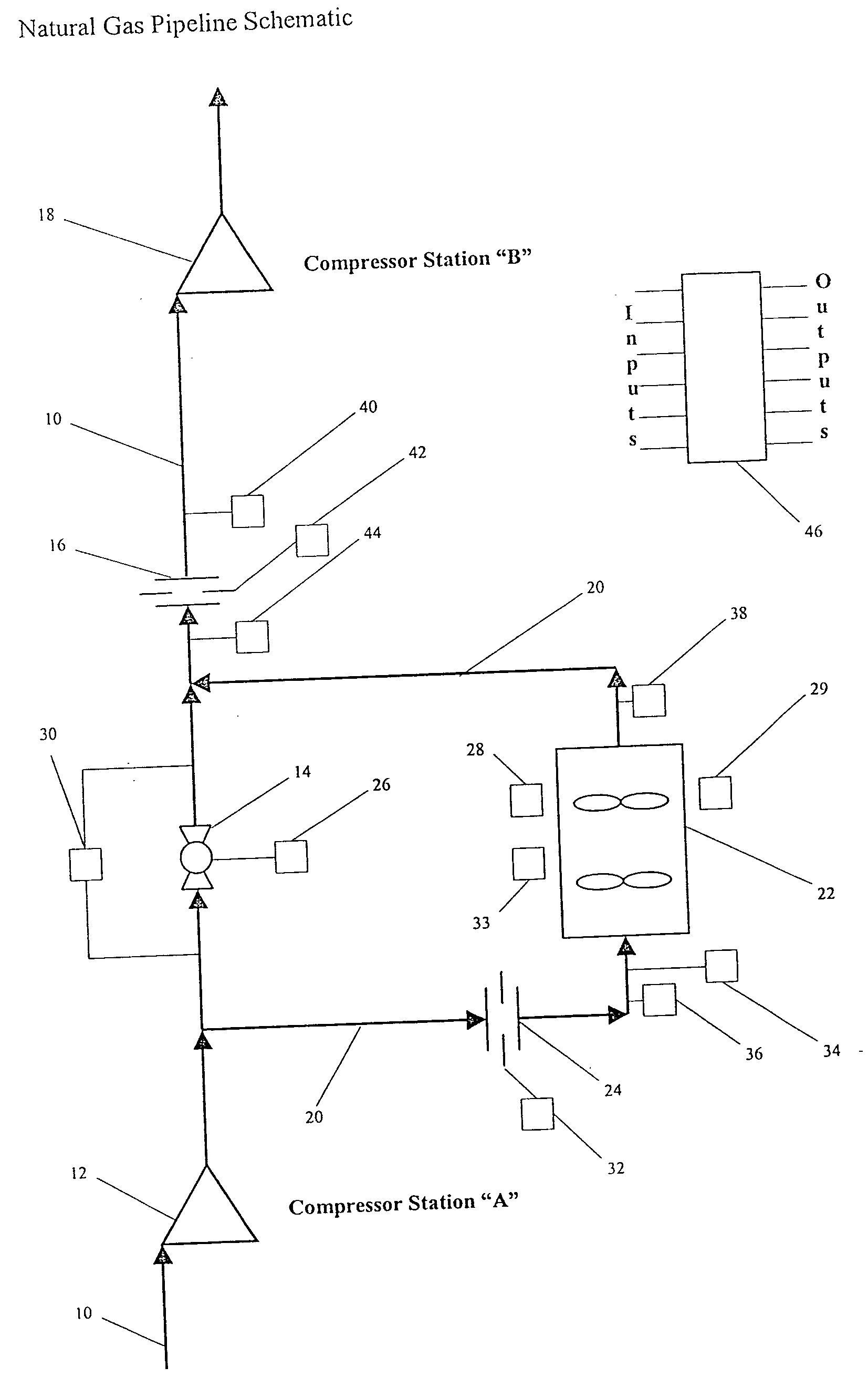
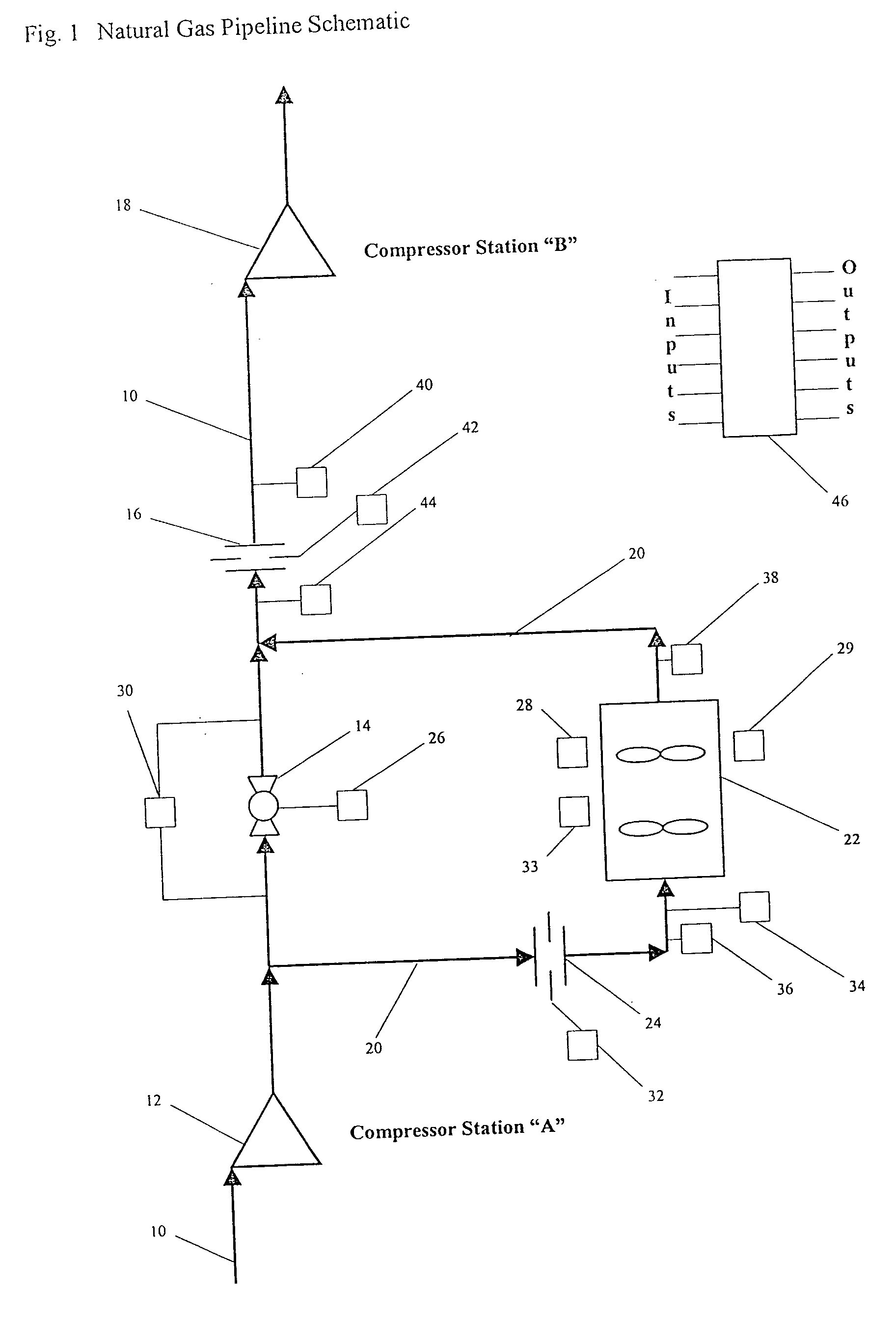
There is therefore provided in accordance with an aspect of the invention, an electronic Heat Exchanger Management Device (HEMD) that determines the optimum balance between gas cooling and heat exchanger pressure loss, for any given operating condition. The HEMD then adjusts the gas flow rate through the exchanger accordingly, to yield the maximum net power (and thereby energy) savings obtainable from that exchanger. The HEMD can maintain the optimum balance between gas cooling and heat exchanger pressure loss and reduce the amount of energy required to transport a given volume of gas through a pipeline and thereby increase the transmission efficiency of the gas pipeline system.

Problems solved by technology

However an increase in gas flow rate also results in a greater pressure loss for the natural gas, and vice versa.

Method used


Image

  • Heat exchanger optimization process and apparatus
  • Heat exchanger optimization process and apparatus
  • Heat exchanger optimization process and apparatus

Examples


Embodiment Construction

In this patent document, the word comprising is used in its inclusive sense and does not exclude other elements being present. The indefinite article “a” before an element does not exclude other elements being present.

The energy required to transport natural gas through a pipeline is stored in the form of gas pressure. Therefore as natural gas is transported along a pipeline it undergoes a pressure loss. The relationship of gas mass flow rate, pipeline inlet gas pressure and temperature to pipeline pressure loss can be defined as follows (based on the AGA Equation for pipeline pressure loss given fully turbulent pipeline flow); Δ⁢ ⁢Pgaspipe=Pgasinlet-(Pgasinlet2-[(mgaspipe)2*(Tgasinlet+Tgasoutlet)*(zgasinlet+zgasoutlet)(2.0615*[TgasstdPgasstd]*[SGgasLpipe]0.5*[log⁢3.7ɛ / dpipe]*dpipe2.5)2])0.5

Given that standard pressure and temperature conditions, and pipeline length, relative roughness and diameter and natural gas specific gravity are constants then the impact of changing gas m...


PUM


Abstract

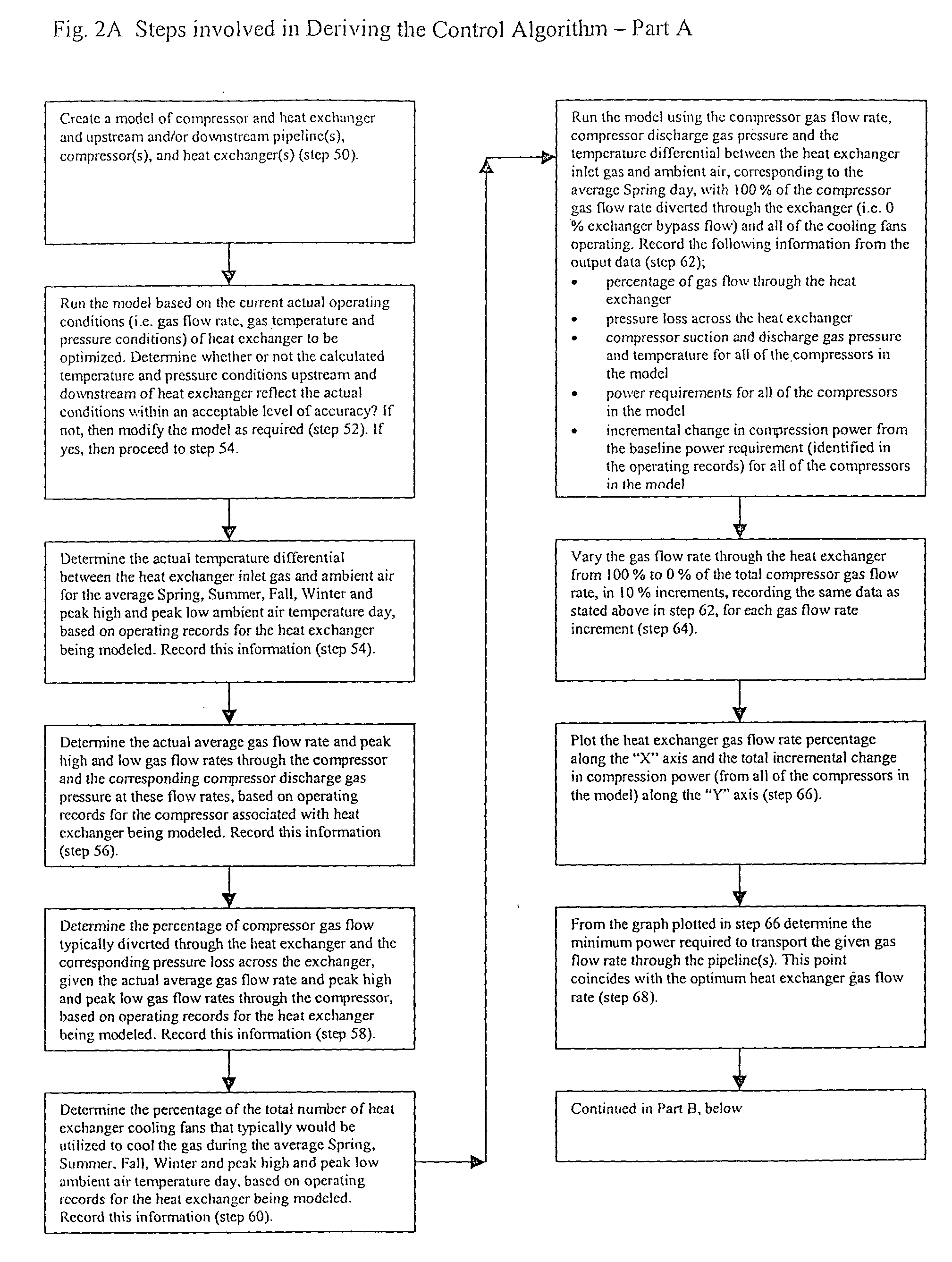
An electronic HEMD determines the optimum balance between gas cooling and heat exchanger pressure loss, for any given operating condition, and adjusts the gas flow rate through the exchanger accordingly, to yield the maximum net power savings (and thereby energy savings) afforded by the exchanger. Maintaining the optimum balance between cooling and exchanger pressure loss reduces the amount of energy required to transport a given volume of gas through a pipeline and thereby increases the transmission efficiency of the gas pipeline system. A method of operating a heat exchanger on a natural gas transmission pipeline using a control algorithm that in turn controls the position of a heat exchanger bypass valve. The current operating conditions of the upstream compressor and gas cooling system are continually monitored for any changes and the control algorithm determines, the optimum flow through the heat exchanger and initiates a command signal to the exchanger bypass valve operator to move the bypass valve and thereby increase or decrease the gas flow rate through the exchanger, as required, until the optimum balance between gas cooling and heat exchanger pressure loss has been achieved.

Description

BACKGROUND OF THE INVENTION The energy required to transport natural gas through a pipeline is stored in the form of gas pressure. Therefore as natural gas is transported along a pipeline it undergoes a pressure loss. For any given pipeline and gas flow rate, the magnitude of the pressure loss is primarily dependent upon the pressure and temperature of the gas flowing through the pipeline. The lower the natural gas pressure and / or higher the temperature, the greater the pipeline pressure loss, and vice versa. In order to maximize natural gas throughput of a pipeline it is necessary to restore the pressure loss (i.e. energy consumed) that occurs as the natural gas travels down a pipeline, by compressing the gas at regular intervals along the pipeline. For any given compressor discharge gas pressure and gas flow rate, the power and thereby energy required to compress the gas is primarily dependent upon the compressor suction gas pressure and temperature (i.e. pipeline outlet gas pre...

Claims


Application Information

Patent Timeline
Patent Type & Authority Applications(United States)
IPC IPC(8): G05B13/02
CPCG05B13/024
Inventor VARNEY, BRIAN WILSON
Owner VARNEY BRIAN WILSON
Why Eureka
Try Eureka