
Extraction apparatus

Inactive Publication Date: 2005-02-17
ENVIROCHASING IP HLDG
View PDF8 Cites 34 Cited by
  • Summary
  • Abstract
  • Description
  • Claims
  • Application Information

AI Technical Summary

Benefits of technology

[0013] Preferably, the shroud is movable to accommodate changes in orientation of the apparatus with respect to the workpiece. In this way, an effective seal can be achieved between the shroud and the workpiece so as to minimise leakage.
[0021] The suction hose and the fluid delivery line may be conveniently connected together for handling as a single unit. This may be achieved by accommodating the fluid delivery line in the suction hose for at least part of the length thereof. The shroud may incorporate a barrier arranged for preventing rubble and other debris generated during operation of the tool from entering the shroud and clogging the extraction line and suction hose connected thereto.
[0022] Water used as the dust suppression fluid may also serve a purpose of lubricating the tool. Additionally, the water content of the slurry may serve to assist cooling of the exhaust fluid, thereby preventing the otherwise hot exhaust fluid from damaging the suction hose.
[0029] The confluence of the incoming air and the hot exhaust gas is advantageous in that contact of the air stream with the hot exhaust gas stream effects cooling of the exhaust gas.
[0038] The apparatus may incorporate a filter or scrubber for treating the exhaust gas before being dispelled. This may allow the hazardous components to be extracted from the exhaust gas before it is dispelled. It may even allow for the exhaust gas to be dispelled within the same environment without increasing the hazard to the operator. This may be particularly useful when the machinery is used in underground locations.
[0041] In the alternative situation, the inlet may be connected to the blower source by way of a blower hose. As the blower hose is connected to the inlet, there is no risk of damage due to hot exhaust gases.

Problems solved by technology

A significant amount of dust can be generated during a chasing operation.
When the slurry dries, it reverts to the dust which can then create further problems.
Furthermore, the use of water to suppress dust precludes the use of electrical machinery, such as electrical grinders which were previously a preferred option for performing chasing operations.
The inability to use electrical machinery requires that other sources of power be utilised.
Such a machine does, however, have a disadvantage in that its exhaust gases are potentially dangerous, particularly when the machine is operated in confined areas.

Method used


Image

  • Extraction apparatus
  • Extraction apparatus
  • Extraction apparatus

Examples


first embodiment

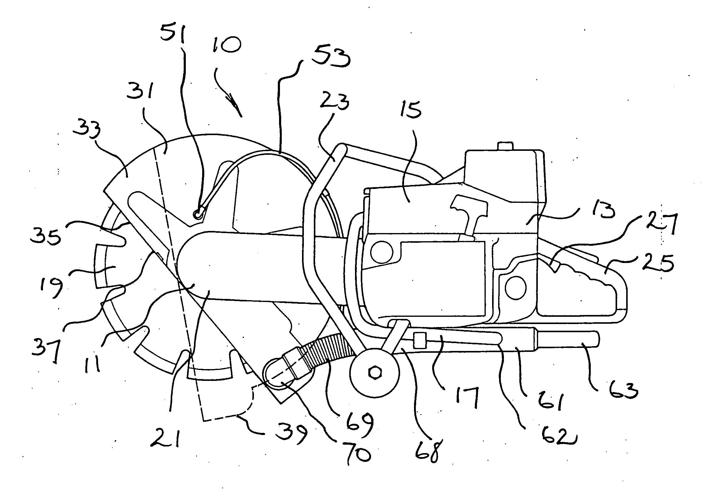
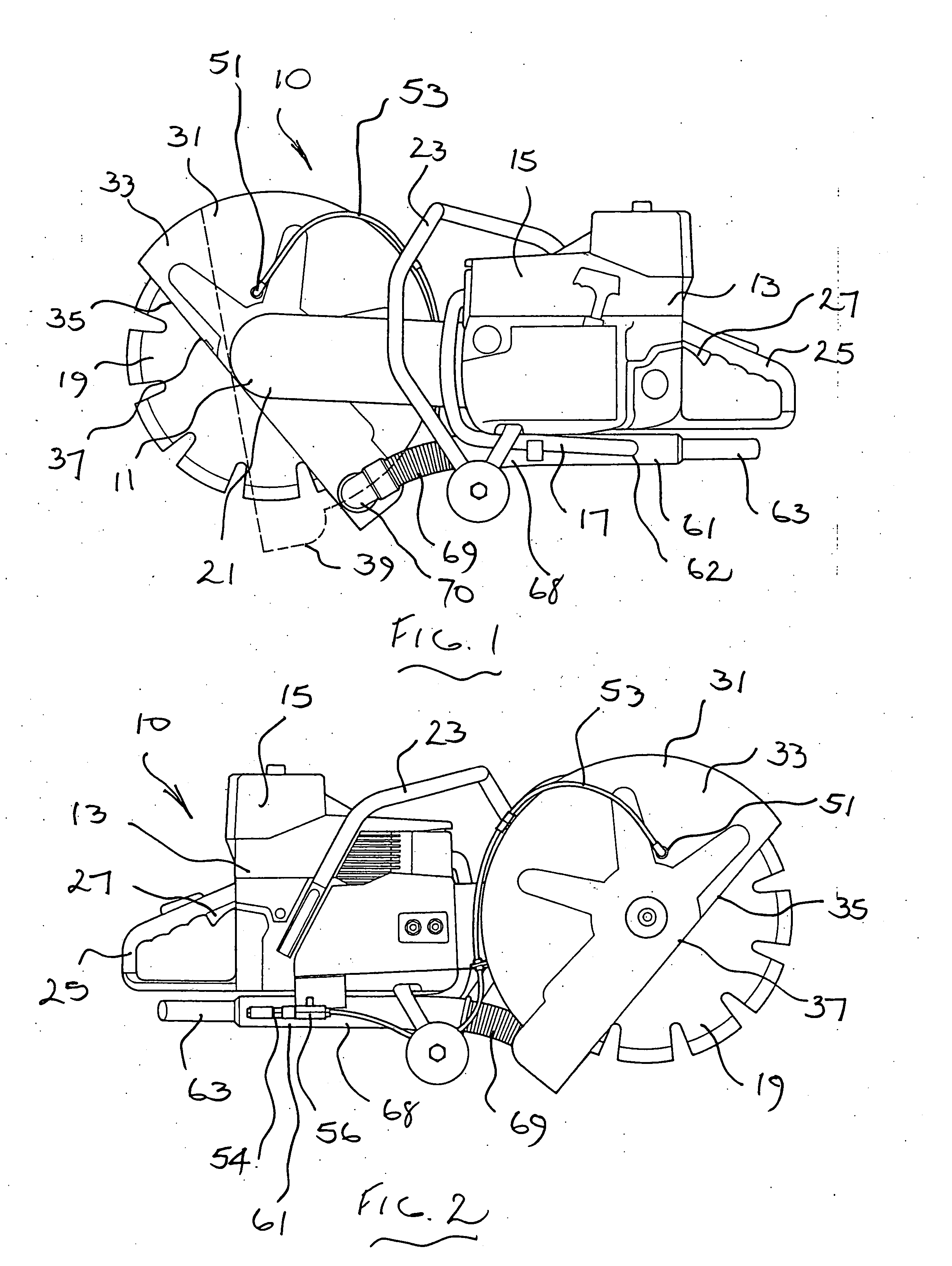
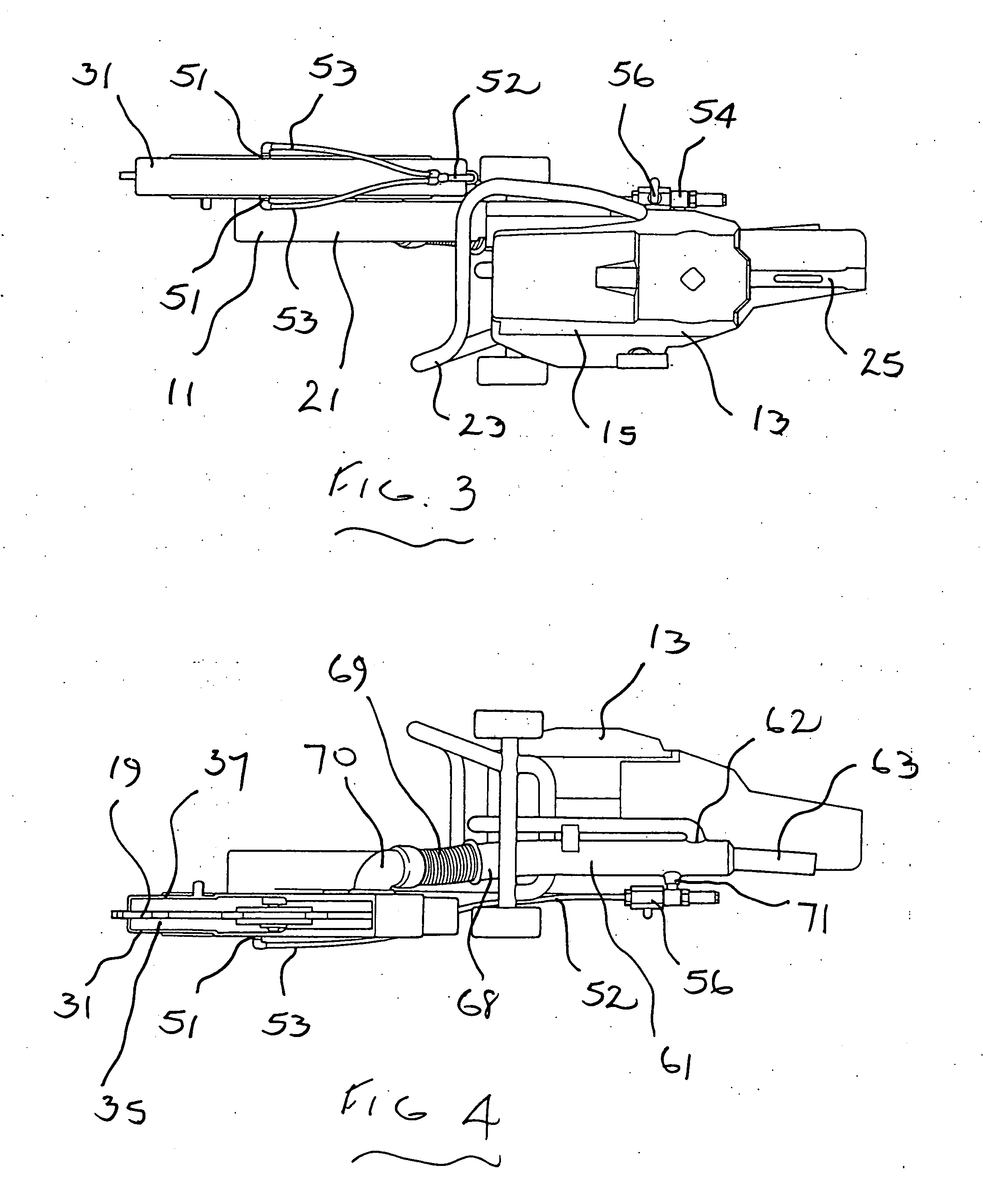
[0059] Referring to FIGS. 1 to 6 of the drawings, there is shown a cutting machine 10 for performing cutting and chasing operations on wall and floor surfaces. In this embodiment, the machine 10 is a hand-held unit.

[0060] The cutting machine 10 comprises a work head 11 and a body 13 carrying the work head 11. The body 13 incorporates a drive unit which in this embodiment is in the form of a petrol engine 15 having an exhaust line 17.

[0061] The drive head 11 receives and supports a cutting tool 19 which in this embodiment is in the form of a cutting blade. The cutting blade 19 is driven by the engine 15 through a drive belt (not shown) enclosed in a guard 21.

[0062] The body 13 is provided with a side handle 23 and a rear handle 25 which incorporates controls including a control trigger 27 for controlling operation of the engine 15.

[0063] A shroud 31 is mounted onto the drive head 11 about the cutting blade 19. The shroud 31 comprises a body 33 which encloses part of the cutting b...

second embodiment

[0079] Referring now to FIGS. 7 and 8, the cutting machine 100 comprises a floor saw 101 of conventional construction movable over a floor surface 103 in which a cutting or chasing operation is to be performed. The floor saw 101 comprises a body 105 supported on wheels 107 for movement over the floor surface 103. The body 105 is fitted with a handle structure 109 by means of which it can be propelled over the floor surface. The floor saw 101 incorporates a drive head (not shown) which receives and supports a cutting tool 111 which is of known kind and which in this embodiment is in the form of a cutting blade. The cutting blade is driven by an engine 113 through a transmission system (not shown) which delivers rotational torque from the engine 113 to the drive head. In this embodiment, the engine 113 is an internal combustion engine operating with gaseous fuel stored in a storage tank 115 carried on the body 105. It will of course be appreciated that the engine may be of any other ...

third embodiment

[0093] Referring to FIGS. 9 and 10 of the drawings, there is shown an extraction apparatus 200 according to a The apparatus 200 is an attachment for a cutting machine (not shown) for performing cutting and chasing operations on wall and floor surfaces.

[0094] The cutting machine typically comprises a work head and a body carrying the work head. The body incorporates a drive unit in the form of an internal combustion engine (typically a petrol engine) having an exhaust line.

[0095] The drive head receives and supports a cutting tool, typically in the form of a cutting blade. A shroud is mounted onto the drive head about the cutting blade. The shroud encloses part of the cutting blade and has an opening beyond which the cutting blade extends. The purpose of the shroud is to contain the dust and, if water is used for dust suppression, to also contain slurry generated by the water used to suppress the dust. Such an arrangement is similar to the cutting machine 10 described in relation t...


PUM

PropertyMeasurementUnit
Flow rateaaaaaaaaaa
Flexibilityaaaaaaaaaa
Heataaaaaaaaaa

Abstract

A machine (10) for performing a working operation such as cutting on a workpiece. The machine (10) has a tool (19) for performing the working operation and a drive motor (13) operable to drive the tool. The drive motor (13) has an exhaust (17) through which an exhaust fluid is discharged during operation. Means (51) are provided for delivering a dust suppression fluid such as water into the vicinity of the tool (19) for suppressing dust generated thereby. A shroud (31) is disposed about the tool (19) for containing dust and the dust suppression fluid, and an extraction line (61) communicates with the shroud (71) for extracting dust and dust suppression fluid contained thereby, as well as air within the shroud. The extraction line (61) further communicates with the exhaust (17) of the drive motor (13) for receiving the exhaust fluid discharging therefrom, the exhaust fluid mixing with the air strength flowing from the shroud.

Description

FIELD OF THE INVENTION [0001] This invention relates to an extraction apparatus and to a machine incorporating such extraction apparatus. [0002] The extraction apparatus according to the invention has been devised particularly, although not solely, for use with a machine which is used to perform cutting and chasing operations on brickwork and masonry and which is powered by an internal combustion engine. With use of the extraction apparatus, exhaust gases generated by such a machine may be dispelled from environments where exhaust build-up may create hazardous working conditions. [0003] The extraction apparatus may also be used to extract exhaust gas from other machinery powered by combustion engines, such as chainsaws and lawnmowers. BACKGROUND ART [0004] It is common to chase a groove or trench into brickwork and masonry to accommodate service lines such as electrical and other cabling, and water and gas supply lines. Typically a chasing operation is performed using a machine havi...

Claims


Application Information

Patent Timeline
IPC IPC(8): B23Q11/00B28D7/02
CPCB23Q11/0046B28D7/02B23Q11/006Y10T83/4696
Inventor TERPSTRA, STEVEN
Owner ENVIROCHASING IP HLDG
Features
  • Generate Ideas
  • Intellectual Property
  • Life Sciences
  • Materials
  • Tech Scout
  • Unparalleled Data Quality
  • Higher Quality Content
  • 60% Fewer Hallucinations
Learn More