Spinning concentrator enhanced solar energy alternating current production

a technology of alternating current and spinning concentrator, which is applied in the direction of lighting and heating apparatus, light radiation electric generator, instruments, etc., can solve the problems of not teaching nor anticipating the application of solar energy conversion to electricity (ac or dc) or any other form of energy, and achieves the effect of inexpensive system for ac photovoltaic conversion

Inactive Publication Date: 2005-02-17
RABINOWITZ MARIO
View PDF20 Cites 21 Cited by
  • Summary
  • Abstract
  • Description
  • Claims
  • Application Information

AI Technical Summary

Benefits of technology

Another object is to provide a fluid for lubricating the mini-mirror elements so that they may rotate freely.
Another object is to provide an inexpensive system for ac photovoltaic conversion.

Problems solved by technology

This prior art application does not in any way deal with the production of alternating current power.
Furthermore the prior art neither teaches nor anticipates application of the conversion of solar energy to electricity (ac or dc) or any other form of energy.

Method used


Image

  • Spinning concentrator enhanced solar energy alternating current production
  • Spinning concentrator enhanced solar energy alternating current production
  • Spinning concentrator enhanced solar energy alternating current production

Examples


Embodiment Construction

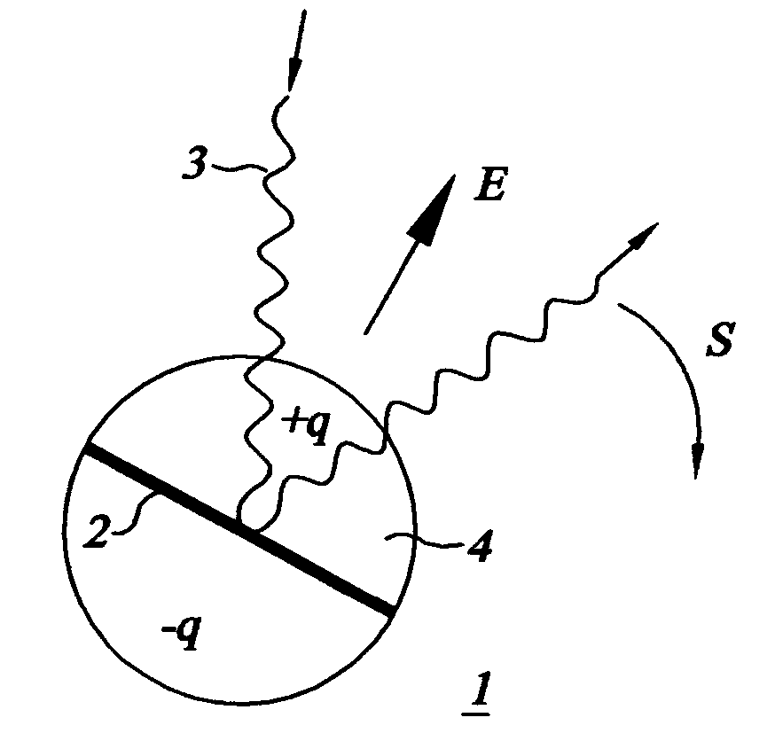
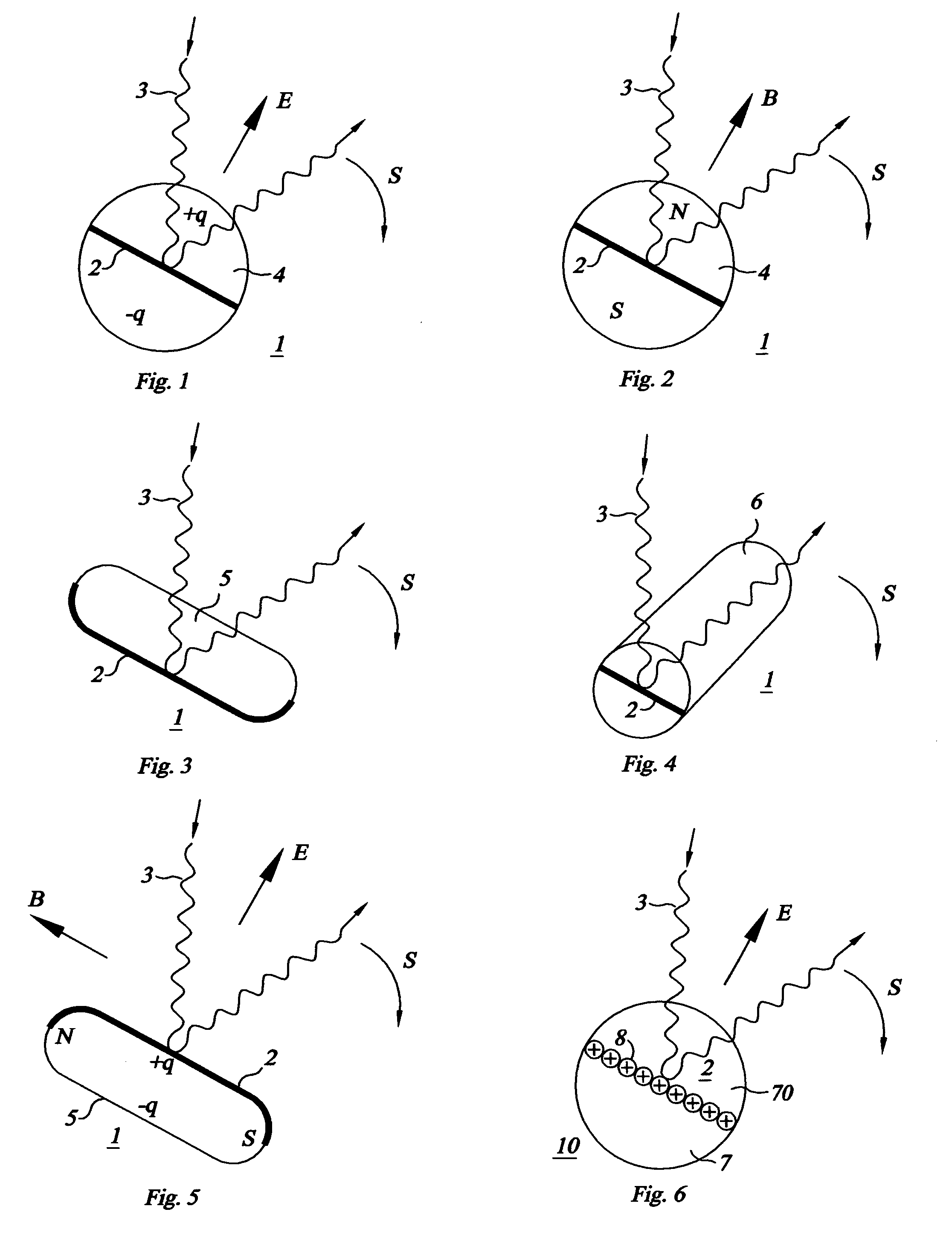
FIG. 1 shows a rotatable element 1 of a focussing planar mini-mirror with an equatorial flat reflecting surface 2 which reflects a ray of sunlight 3. The reflecting surface 2 preferably reflects on both sides. The element 1 shown is a cross-sectional view of an electrically charged bipolar spheroid 4 with charge +q in one hemisphere and charge −q in the opposite hemisphere, that is operated in the well-known electrical gyricon mode. This spheroid 4 is one of a multitude of rotatable optical elements 1 which track the sun and focus the sunlight onto a collector by means of an electric field E. A charged electric dipole may also be entirely present in only one hemisphere for the purposes of tracking the sun and / or spinning. Once the primary orientation of each reflecting surface 2 is determined, the direction of the electric field can be rapidly rotated about the primary orientation causing the elements 1 to spin as shown by the curved arrow labeled S.

FIG. 2 shows a rotatable element ...


PUM


Abstract

Due to an ever growing shortage of conventional energy sources, there is an increasingly intense interest in harnessing solar energy. This invention deals with method and apparatus for the direct conversion of solar energy to alternating current power by an active spinning mini-optics system. A limiting factor in the utilization of solar energy in the past has been the high cost of power conversion from dc to ac. By directly producing alternating current power, this invention substantially reduces the cost of generating photovoltaic electricity. This system utilizes a dynamic spinning ensemble of mini-mirrors to both concentrate and modulate rays from the sun onto a photovoltaic collector array. The focusing with superimposed spinning action produces single phase and multiphase alternating current (ac) with substantially higher power output than the direct current (dc) power resulting from the direct incidence of sunlight on the photovoltaic collector.

Description

BACKGROUND OF THE INVENTION 1. Field Of The Invention This invention relates generally to method and apparatus for the direct conversion of solar energy to alternating current power by an active spinning mini-optics system. This system utilizes a dynamic spinning ensemble of mini-mirrors to both concentrate and modulate rays from the sun onto a photovoltaic collector array. The spinning of mini-reflectors with superimposed dc bias produces alternating current (ac) with substantially higher power output than the direct current (dc) power resulting from the direct incidence of sunlight on the photovoltaic collector. Due to an ever growing shortage of conventional energy sources, there is an increasingly intense interest in harnessing solar energy. A limiting factor in the utilization of solar energy has been the high cost of power conversion from dc to ac. This invention provides a low cost means for achieving affordable solar energy by greatly reducing the cost of solar concentrat...

Claims


Application Information

Patent Timeline
Patent Type & Authority Applications(United States)
IPC IPC(8): G02B26/02H02N6/00
CPCF24J2/16F24J2002/1066F24J2002/108H02S99/00Y02E10/40Y02E10/52G02B26/026F24S23/77F24S2023/85F24S2023/872Y02E10/50
Inventor RABINOWITZ, MARIO
Owner RABINOWITZ MARIO
Why Eureka
Try Eureka