
Fire resistant base tank for mounting a generator

a base tank and generator technology, applied in the direction of packaging foodstuffs, container discharge methods, packaging goods, etc., can solve the problems of increasing the cost and complexity of installation, limiting the equipment that may be used for positioning, and increasing the footprint of the base tank

Active Publication Date: 2005-02-17
RING POWER
View PDF22 Cites 3 Cited by
  • Summary
  • Abstract
  • Description
  • Claims
  • Application Information

AI Technical Summary

Benefits of technology

[0019] The fire resistant solution can be removed for inspection or repair of the tank at the site. A leak detection system with a level sensor is located in the interstitial space and can detect a leak in the outer tank or in the inner tank. A water detection system may also be located in the inner tank to detect leaks. An antifreeze solution is optionally added to the fire resistant solution to protect the solution from freezing in cold climates.
[0027] A further aspect is a fire resistant solution consisting of at least two percent fire blocking gel and at least eighty-eight percent water. In one mode, the fire resistant solution is BARRICADE™. In another mode, the fire resistant solution can be modified to prevent freezing during cold temperatures. In a further mode, the fire resistant solution contains up to ten percent propylene glycol to prevent freezing.

Problems solved by technology

Space for installation and access for auxiliary generators is often constrained by site features and facility design, limiting the equipment that may be used for positioning.
Increased tank weight increases cost and complexity of installation, however.
The relatively large interstitial space required for solid insulating material significantly increases the footprint of the base tank and decreases fuel volume for a given installation space.
Furthermore, once installed, solid insulating material cannot be easily removed from the interstitial space for inspection or repair.
The concrete works well as a fire shield, however, the concrete also makes the tank extremely heavy and cumbersome to transport and install.
Further, once the concrete has hardened, it cannot be readily removed for tank inspection or repair.
McGarvey does not, however, teach a combination of exterior fire resistant material, interstitial insulation and support structure necessary to function as a generator base tank.
Furthermore, McGarvey does not teach a non-solid insulation material for the interstitial space.
Although several above-referenced patents suggest materials other than A-36 mild steel for tank walls, such as plastic, fiberglass, or corrosion resistant steel, they do not suggest any particular type of steel that would provide the combined advantage of improved heat conduction, impact resistance, and as corrosion resistance to a water base fire resistant solution in the interstitial space.
In fact, the corrosion resistant steels described do not exhibit those properties.
These stiffening members provide support for the generator, however this external support configuration adds significant weight and size to the tank system and can interfere with generator maintenance access.
However, none of the patents referenced above suggest the use of baffles in the inner tank as a means of support for the generator.

Method used


Image

  • Fire resistant base tank for mounting a generator
  • Fire resistant base tank for mounting a generator
  • Fire resistant base tank for mounting a generator

Examples


Embodiment Construction

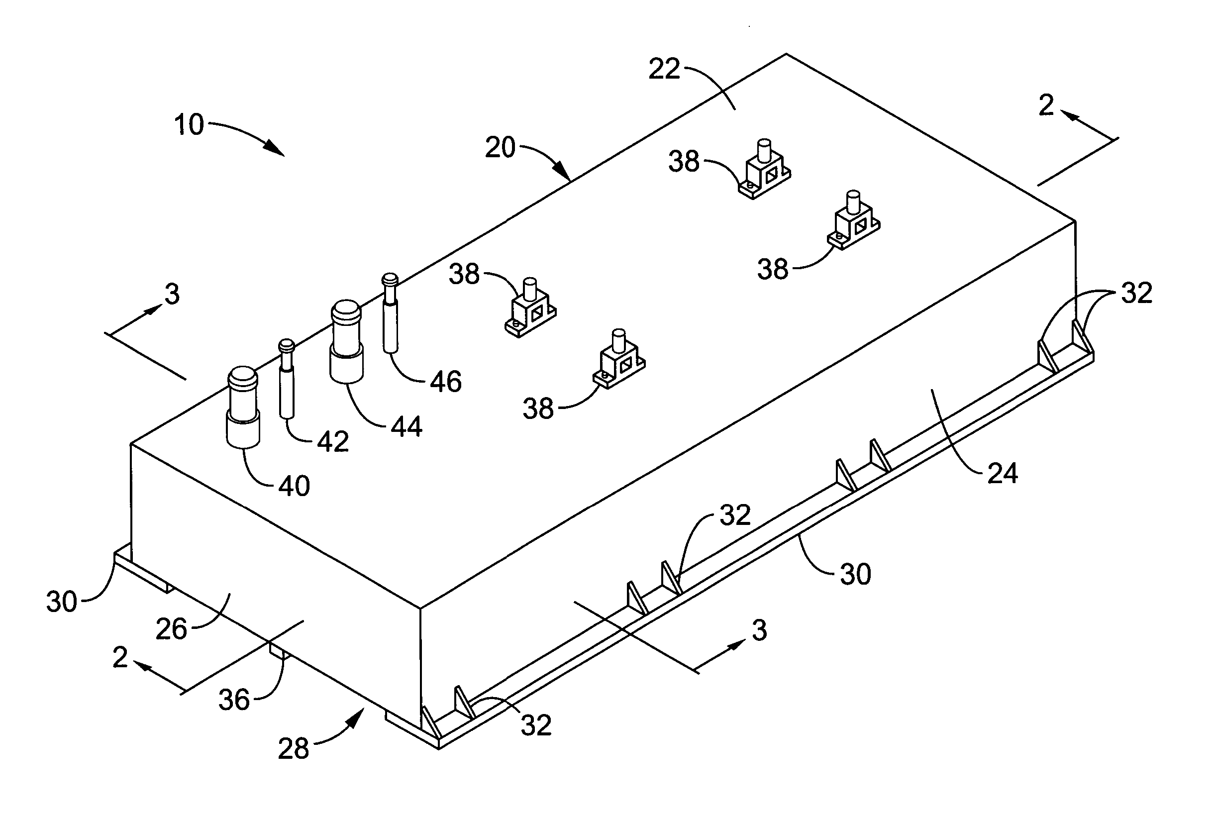
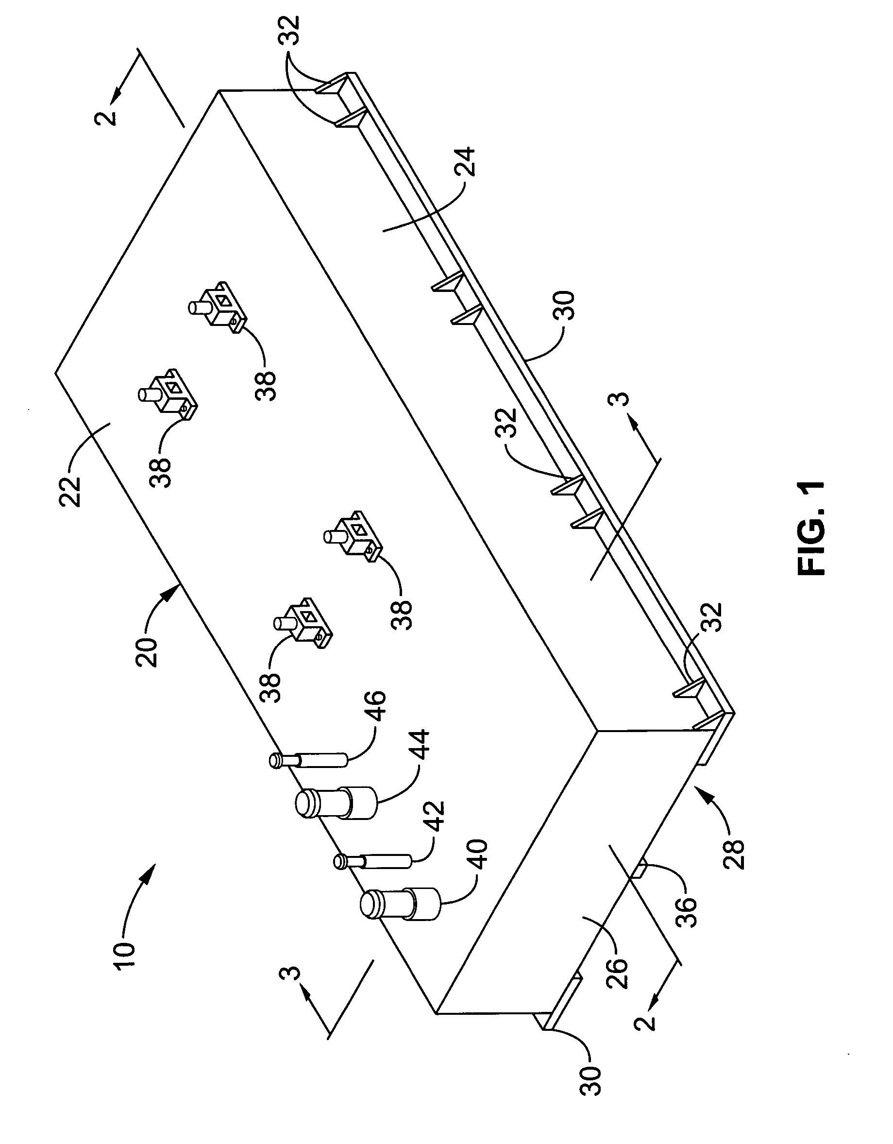
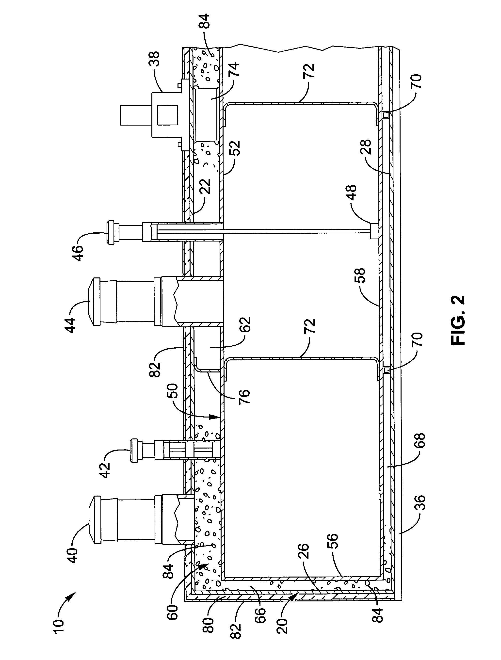
[0038] Referring more specifically to the drawings, for illustrative purposes the present invention is embodied in the apparatus generally shown in FIG. 1 through FIG. 5. It will be appreciated that the apparatus may vary as to configuration and as to details of the parts, and that the method may vary as to the specific steps and sequence, without departing from the basic concepts as disclosed herein. All joints are typically made with welds unless otherwise specified.

[0039]FIG. 1 is a perspective view of the exterior of a fire resistant base tank assembly 10 before a fire resistant coating (shown in FIG. 2 and FIG. 3) is applied. Details of tank components such as ports for instrumentation, fuel supply, fuel return and venting, brackets for lifting and securing, and tank cut outs for electrical connections, as are known in the art, are omitted for clarity. Base tank assembly 10 comprises an outer tank 20 and an inner tank 50 which are positioned and configured as will be more full...


PUM


Abstract

An above-ground, double-walled, tank for holding combustible material and supporting a generator has an outer tank and an inner tank with structural baffles, all made from type 316 stainless steel. An interstitial space formed by the outer tank and inner tank is filled with a fire resistant solution consisting of a fire block gel and water. An internal support system, including structural baffles in the inner tank, provide a structure to support a generator and other equipment on the top of the tank without the use of tank wall stiffeners or external beams. A level detector in the interstitial space detects changes in the level of the fire resistant solution. A water detector in the inner tank detects the presence of water. The fire resistant solution may be removed from the interstitial space for tank inspection and repair.

Description

CROSS-REFERENCE TO RELATED APPLICATIONS [0001] This application claims priority from U.S. provisional application Ser. No. 60 / 410,869 filed on Sep. 12, 2002, incorporated herein by reference.STATEMENT REGARDING FEDERALLY SPONSORED RESEARCH OR DEVELOPMENT [0002] Not Applicable INCORPORATION-BY-REFERENCE OF MATERIAL SUBMITTED ON A COMPACT DISC [0003] Not Applicable BACKGROUND OF THE INVENTION [0004] 1. Field of the Invention [0005] This invention pertains generally to above ground fuel tanks for generators, and more particularly to a lightweight, low profile base tank with fire resistive, impact resistive and leak protection elements. [0006] 2. Description of Related Art [0007] Many auxiliary generators that provide remote or backup power are mounted on a base tank as an integrated system. The base tank is required to provide sufficient fuel to the generator system to run for extended periods of time without refueling. Space for installation and access for auxiliary generators is ofte...

Claims


Application Information

Patent Timeline
IPC IPC(8): B65DB65D90/02B65D90/22
CPCB65D90/22B65D90/028
Inventor RODGERS, JERRY W.BUSKE, SCOTT E.
Owner RING POWER
Learn More