

Strained channel complementary field-effect transistors and methods of manufacture
- Summary
- Abstract
- Description
- Claims
- Application Information
AI Technical Summary
Benefits of technology
Problems solved by technology
Method used
Image

Examples
Embodiment Construction
[0019] The making and using of the presently preferred embodiments are discussed in detail below. It should be appreciated, however, that the present invention provides many applicable inventive concepts that can be embodied in a wide variety of specific contexts. The specific embodiments discussed are merely illustrative of specific ways to make and use the invention, and do not limit the scope of the invention.
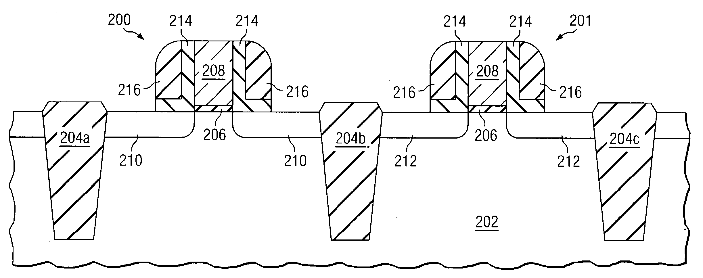
[0020] The preferred embodiment of the present invention relates to the field of semiconductor devices, and more specifically, to the manufacture of strained n-channel and p-channel field effect transistors with separately optimized performance.
[0021] With the preferred embodiment it is possible to separately optimize the performance of n-channel and p-channel transistors by engineering the nature and magnitude of the strain in the channel region of the transistors. For example, it is desirable to induce a tensile strain in the channel of the n-channel transistor in the so...
PUM
 Abstract
Description
Claims
Application Information