
Device for generating line-shaped light beam and laser microscope

a laser microscope and light beam technology, applied in the field of laser microscopes, can solve the problems of high manufacturing cost of the microscope, high cost of the acoustic-optical element which deflects the laser beam in the main scanning direction, and the device has been enlarged

Active Publication Date: 2005-02-17
OHKURA IND
View PDF6 Cites 14 Cited by
  • Summary
  • Abstract
  • Description
  • Claims
  • Application Information

AI Technical Summary

Benefits of technology

[0009] The present invention has for its object to provide a laser microscope which uses no acoustic-optical elements, and which is low in manufacturing costs and small and compact in structure.
[0010] Another object of the present invention is to provide a laser microscope in which no glaring or speckle patterns are formed even if a laser source is used as a light source for emitting a light beam, and which can pick up high-quality images.
[0011] Yet another object of the present invention is to provide an optical device for emitting a rectilinear light beam which can produce an incoherent rectilinear light beam having thin elongated cross section and which can be applied to various optical scanning devices.

Problems solved by technology

Although the laser microscope using the laser beam has an advantageous effect capable of picking up a high-resolution image, a disadvantage of high manufacturing cost of the microscope has been pointed out, because the cost of the acoustic-optical element which deflects the laser beam in the main scanning direction is extremely high.
There has been another disadvantage that because of a relatively small beam deflection angle of the acousto-optic element, an optical path length of the optical system must be made longer in order to obtain a desired scanning length on the sample, and consequently the microscope device has been enlarged.
For example, in the case of a color microscope, acoustic-optical elements having different set conditions must be prepared for each color light, which has caused high manufacturing costs.
However, in the case of using the rectilinear beam produced by cylindrical lens, because of high coherence of the laser beam, many speckle patterns are generated in the rectilinear beam, and thus a high-quality image cannot be picked up.
However, because the mercury lamp is large in size and high in price, there is a disadvantage that the size of the microscope is enlarged and manufacturing costs become high.

Method used


Image

  • Device for generating line-shaped light beam and laser microscope
  • Device for generating line-shaped light beam and laser microscope
  • Device for generating line-shaped light beam and laser microscope

Examples


Embodiment Construction

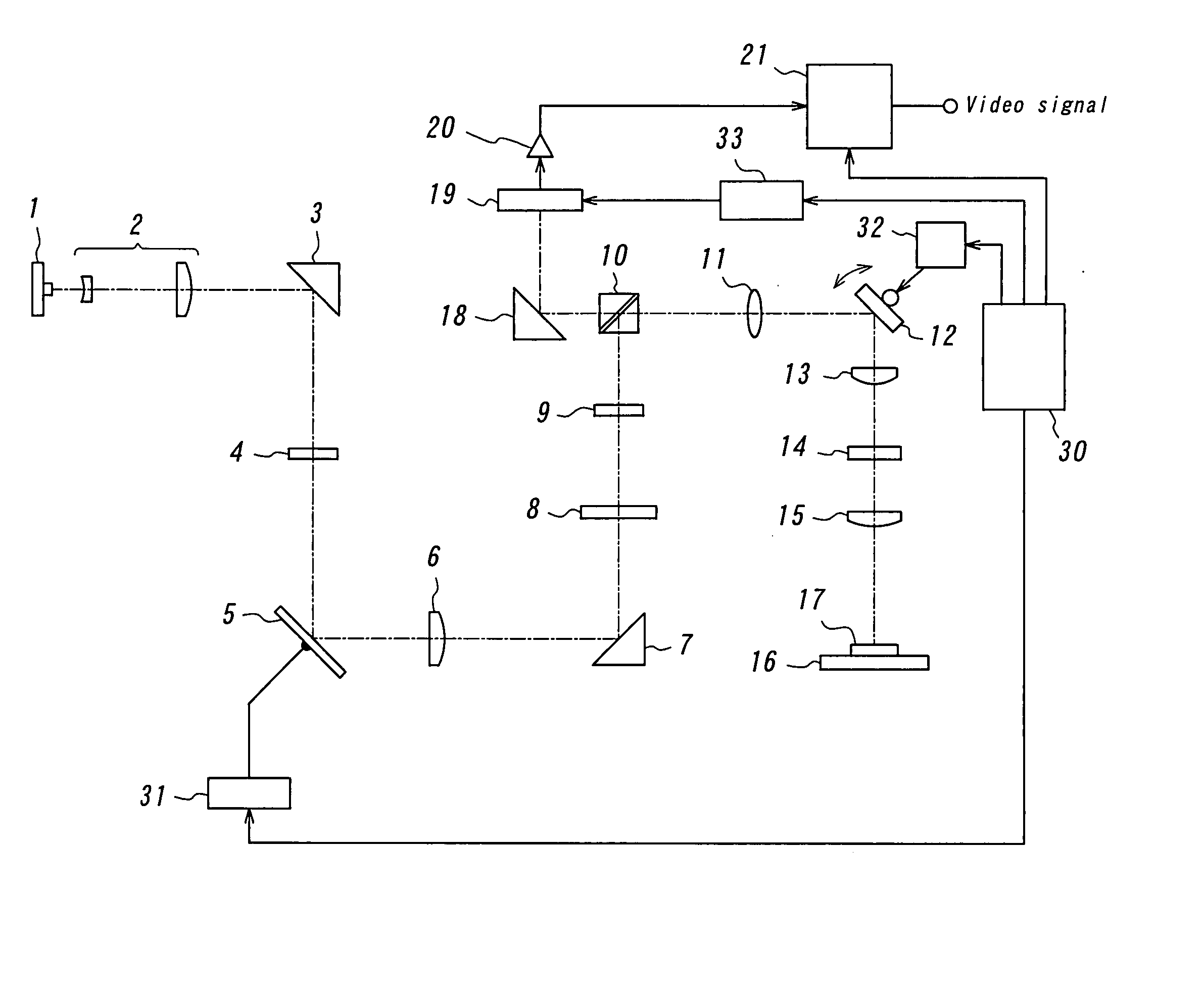
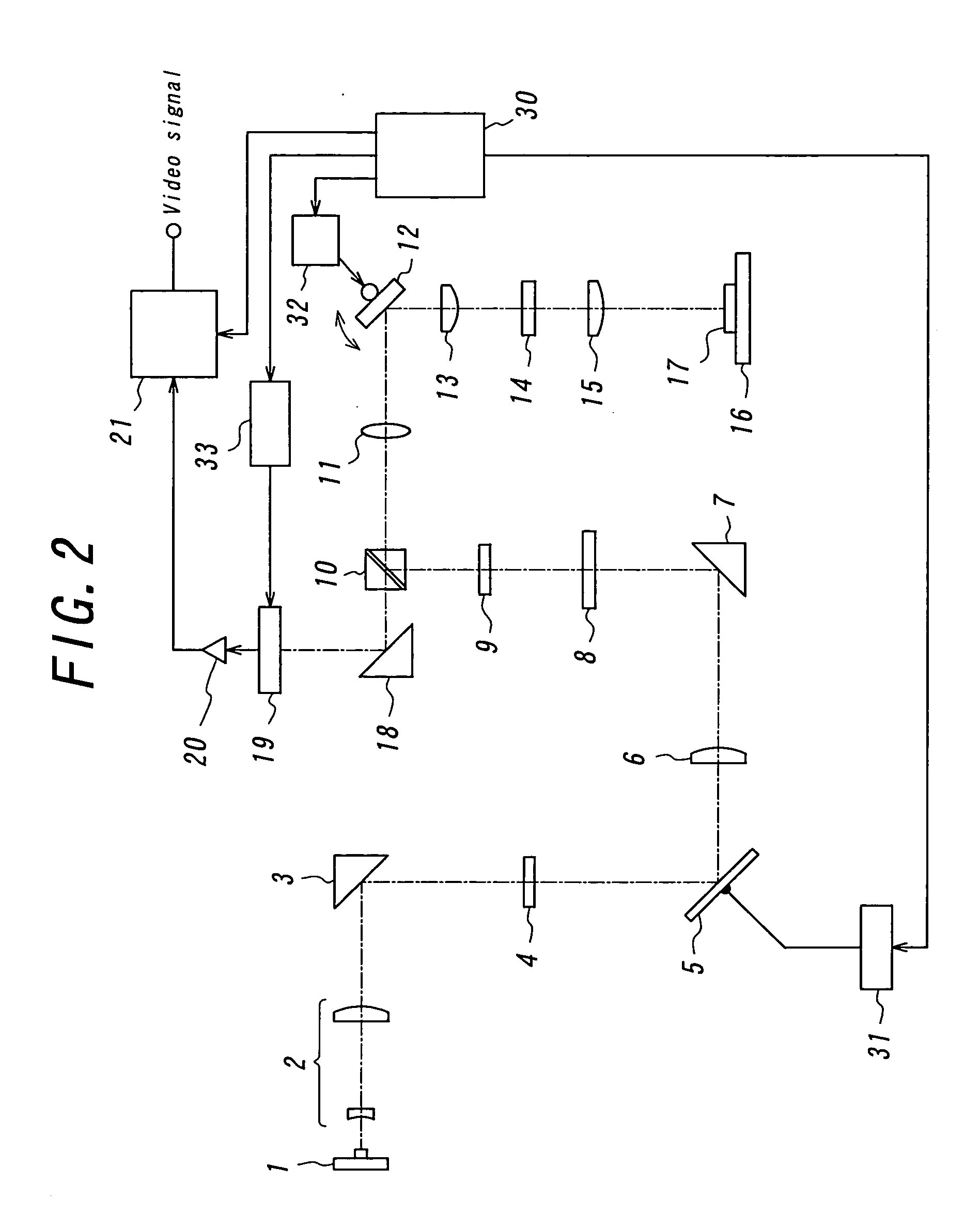
[0032]FIG. 2 is a diagram showing an example of a laser microscope of the present invention. According to the invention, a semiconductor laser is used as a light source for generating a light beam. A laser beam emitted from a semiconductor laser 1 is converted into expanded parallel beam by an expander optical system 2, reflected by a total reflection prism 3, and is made incident upon a first cylindrical lens 4. The first cylindrical lens 4 focuses the incident light beam only in a direction perpendicular to a first direction which is an extension direction of a later-described rectilinear scanning beam. The first cylindrical lens 4 images the incident laser beam onto a mirror surface of a micromirror device 5. Accordingly, a focused line-shaped laser beam strikes the mirror surface of the micromirror device 5. The first cylindrical lens 4 is not an essential component of the invention, but disposed when necessary.

[0033] As described above, the micromirror device 5 comprises a plu...


PUM


Abstract

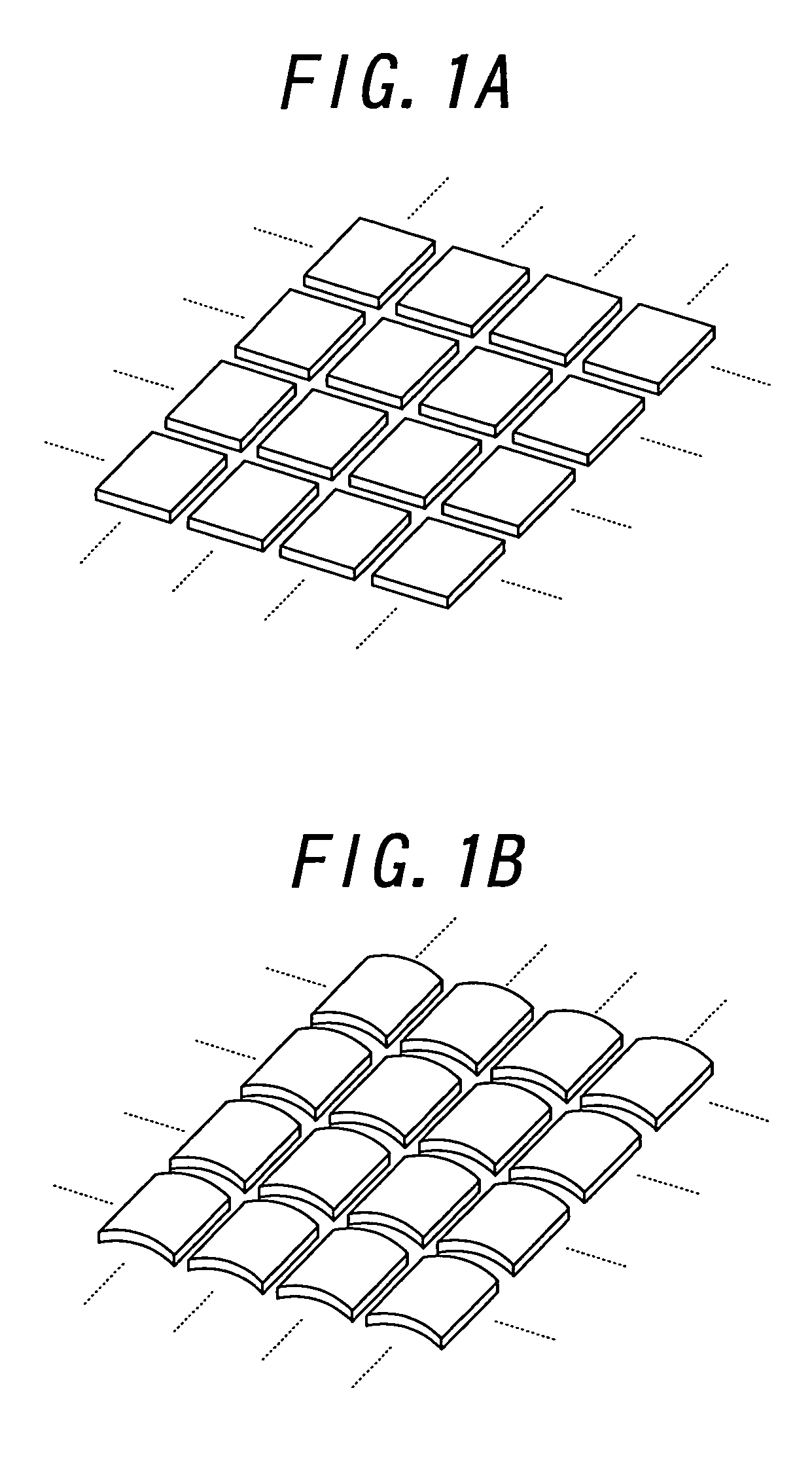
A laser microscope is provided, which is low in manufacturing costs and compact in structure. A laser beam emitted from a semiconductor laser is converted into a rectilinear light beam which has divergence in one direction by use of a micromirror device. The micromirror device comprises a plurality of micromirrors arranged in a two-dimensional array, and each micromirror is vibrated at a high speed by a driving pulse. Since each micromirror is movably supported by a hinge, a mirror layer of the micromirror is displaced in a curved manner by the electrostatic attractive force caused by the driving pulse. By this curved displacement of the mirror layer, each micromirror operates as a cylindrical mirror to convert an incident laser beam into an incoherent light beam which diverges in one direction. The rectilinear beam is projected to a sample through a beam deflection device and an objective lens, and a reflected light from the sample is made incident on a linear image sensor. Since the micromirror device is relatively low in costs and a relatively large diverging angle is obtained, the laser microscope low in manufacturing costs and compact in structure can be achieved.

Description

BACKGROUND OF THE INVENTION [0001] 1. Field of the Invention [0002] The present invention relates to a laser microscope which uses a micromirror device. [0003] The present invention also relates to a device for generating line-shaped light beam having a thin elongated cross section, which converts a laser beam emitted from a laser light source into an incoherent line-shaped light beam by use of the micromirror device. [0004] 2. Description of the Related Art [0005] There has been known a laser microscope in which a surface of a sample to be observed is scanned two-dimensionally by a laser beam and reflected light from the sample is received by a linear image sensor. In such laser microscope, a laser beam generated from a laser light source is deflected in a main scanning direction at a high speed by an acoustic-optical element and deflected in a sub-scanning direction perpendicular to the main scanning direction using a galvano-mirror, whereby the surface of the sample is two-dimens...

Claims


Application Information

Patent Timeline
Patent Type & Authority Applications(United States)
IPC IPC(8): G02B21/00G02B21/06G02B27/09
CPCG02B27/0933G02B21/002
Inventor AWAMURA, DAIKICHI
Owner OHKURA IND
Learn More