Free space optical bus

a free space optical bus and optical bus technology, applied in the field of communication systems, can solve the problems of affecting the data rate of the difficulty of increasing the need for interboard connections using conventional technology, and the difficulty of assembly, so as to achieve the effect of increasing the data rate across the connector

Active Publication Date: 2005-02-17
NORTHROP GRUMMAN SYST CORP
View PDF19 Cites 24 Cited by
  • Summary
  • Abstract
  • Description
  • Claims
  • Application Information

AI Technical Summary

Benefits of technology

[0010] In accordance with yet another aspect of the present invention, a free space optical bus system is provided. The system comprises means for combining a plurality of low data rate signals into a high data rate signal. The system also includes means for transmitting the high data rate signal across a free space gap as an optical signal. The system further comprises means for dividing the high data rate signal back into the plurality of low data rate signals.

Problems solved by technology

The increased need for interboard connections is difficult to satisfy using conventional technology.
Higher interconnect densities lead to a greater possibility of cross talk and difficulties in assembly, as the fine pitch of the connectors require precise alignment with their respective pads on the board across the total length of the connector.
Attempts to increase the data rates across the connectors are hampered by the dielectric and resistance losses experienced by conventional interconnect media at increased frequencies.
Systems using low voltage differential signaling further compound the problem, requiring two interconnections to carry each signal.
These efforts have met with qualified success, but suffer from attenuation problems at high data rates over a distance.
The prior art has yet to provide an efficient, high data rate bus that is effective for a complex digital system.
A related problem can be found in providing connections to hardware that introduces instability into its environment.
For example, the operation of an antenna can produce significant thermal stresses in surrounding circuitry.
These thermal stresses can negatively impact the efficiency and the reliability of surrounding components, leading to increased signal attenuation, especially for high frequency signals.
If the destabilizing device requires a large number of electrical connections, producing an effective alignment of connectors that will minimize the attenuation and reflection of signals within the connections becomes a difficult and time consuming process.

Method used


Image

  • Free space optical bus
  • Free space optical bus
  • Free space optical bus

Examples


Embodiment Construction

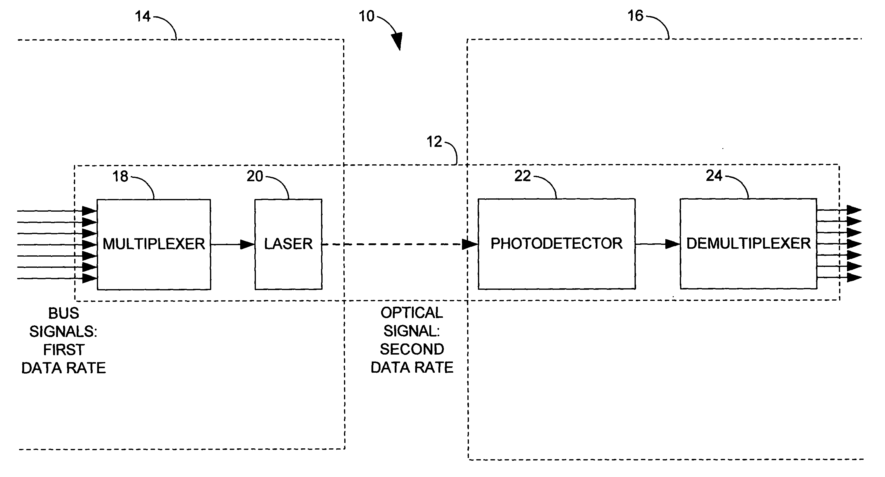
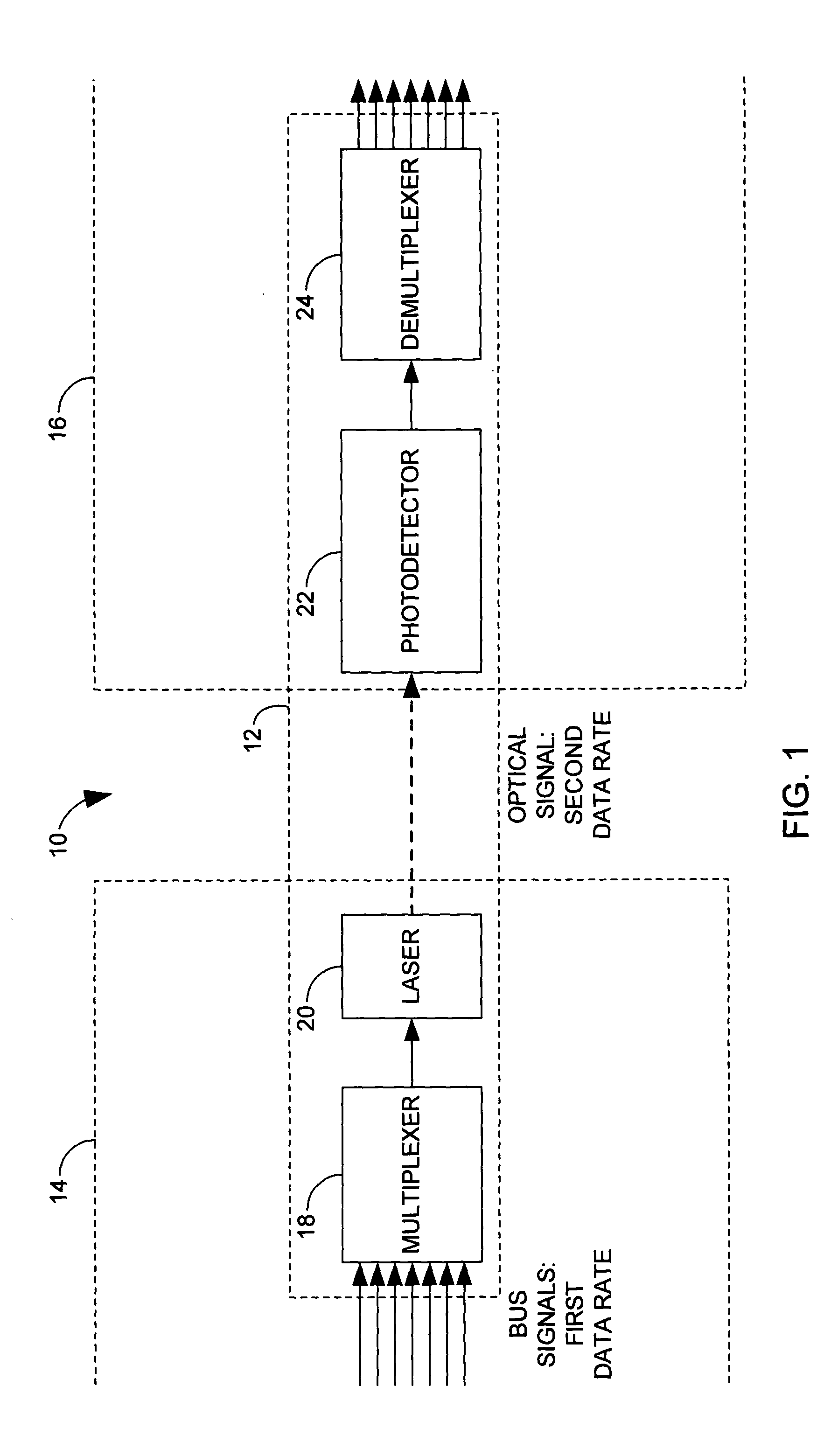
[0020] The present invention relates to a system and method for transferring one or more information carrying signals across a free space gap as part of an optical bus. In accordance with an aspect of the present invention, a plurality of bus signals are multiplexed into a combined signal, which is used to drive a laser. The laser produces an optical signal that is transmitted across a free space gap. The optical signal is received across a free space gap at a receiver. The optical signal is transformed back into an electrical signal, and demultiplexed to recover its constituent signals.

[0021] The present invention enjoys several advantages over the prior art. For example, signals transmitted over copper wire attenuate over distance at a rate that varies with the frequency of the signal. Accordingly, a high data rate cannot be sustained over copper media for long distances. Free space optical signals avoid these attenuation problems. To the extent that there are attenuation problem...


PUM


Abstract

A free space optical bus system and method are provided for connecting two units of circuitry across a free space gap. A first unit of circuitry includes a multiplexer that combines a plurality of bus signals to obtain an electronic combined signal and a laser that is driven by the electronic combined signal to transmit an optical signal. A second unit of circuitry is separated from the first unit of circuitry by a free space gap. The second unit of circuitry includes a photodetector that receives the optical signal and transforms it into an electronic composite signal and a demultiplexer that divides the composite signal into a plurality of constituent signals.

Description

TECHNICAL FIELD [0001] The present invention relates generally to communications systems, and more particularly to a free space optical bus. BACKGROUND OF THE INVENTION [0002] In the past several years, there has been a significant increase in the capacities of integrated circuit boards. As the capacities of individual boards have increased, greater numbers of high data rate interconnections between boards have become necessary. The increased need for interboard connections is difficult to satisfy using conventional technology. Higher interconnect densities lead to a greater possibility of cross talk and difficulties in assembly, as the fine pitch of the connectors require precise alignment with their respective pads on the board across the total length of the connector. Attempts to increase the data rates across the connectors are hampered by the dielectric and resistance losses experienced by conventional interconnect media at increased frequencies. [0003] Conventionally, signals ...

Claims


Application Information

Patent Timeline
Patent Type & Authority Applications(United States)
IPC IPC(8): H04B10/10H04B10/00H04B10/118H04B10/22
CPCH04B10/801
Inventor BJORNDAHL, WILLIAM D.BERENZ, JOHN JOSEPH
Owner NORTHROP GRUMMAN SYST CORP
Why Eureka
Try Eureka