

Sharp end, multi-layer carbon nano-tube radial aggregate and method of manufacturing the aggregate
- Summary
- Abstract
- Description
- Claims
- Application Information
AI Technical Summary
Benefits of technology
Problems solved by technology
Method used
Image

Examples
examples
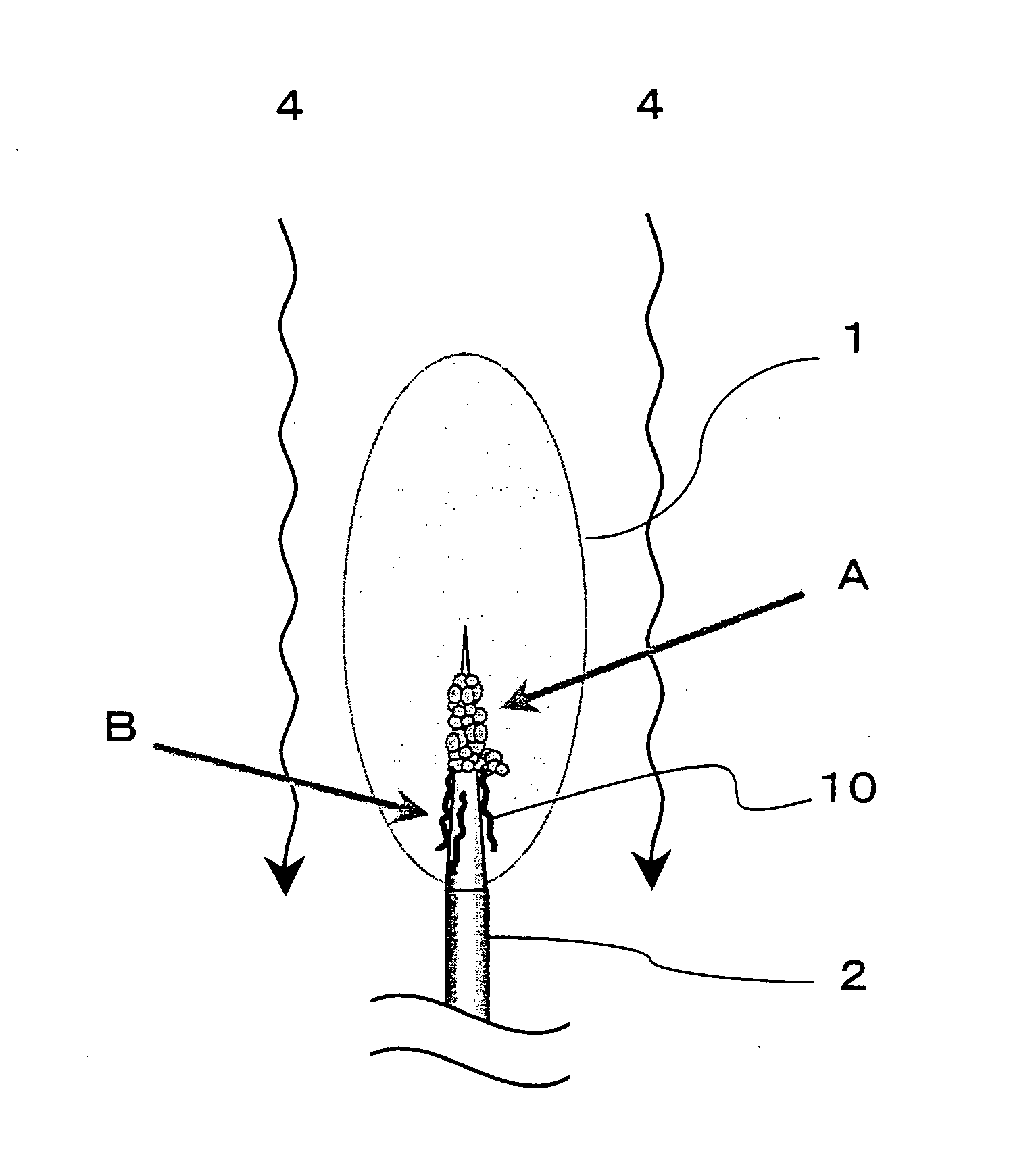
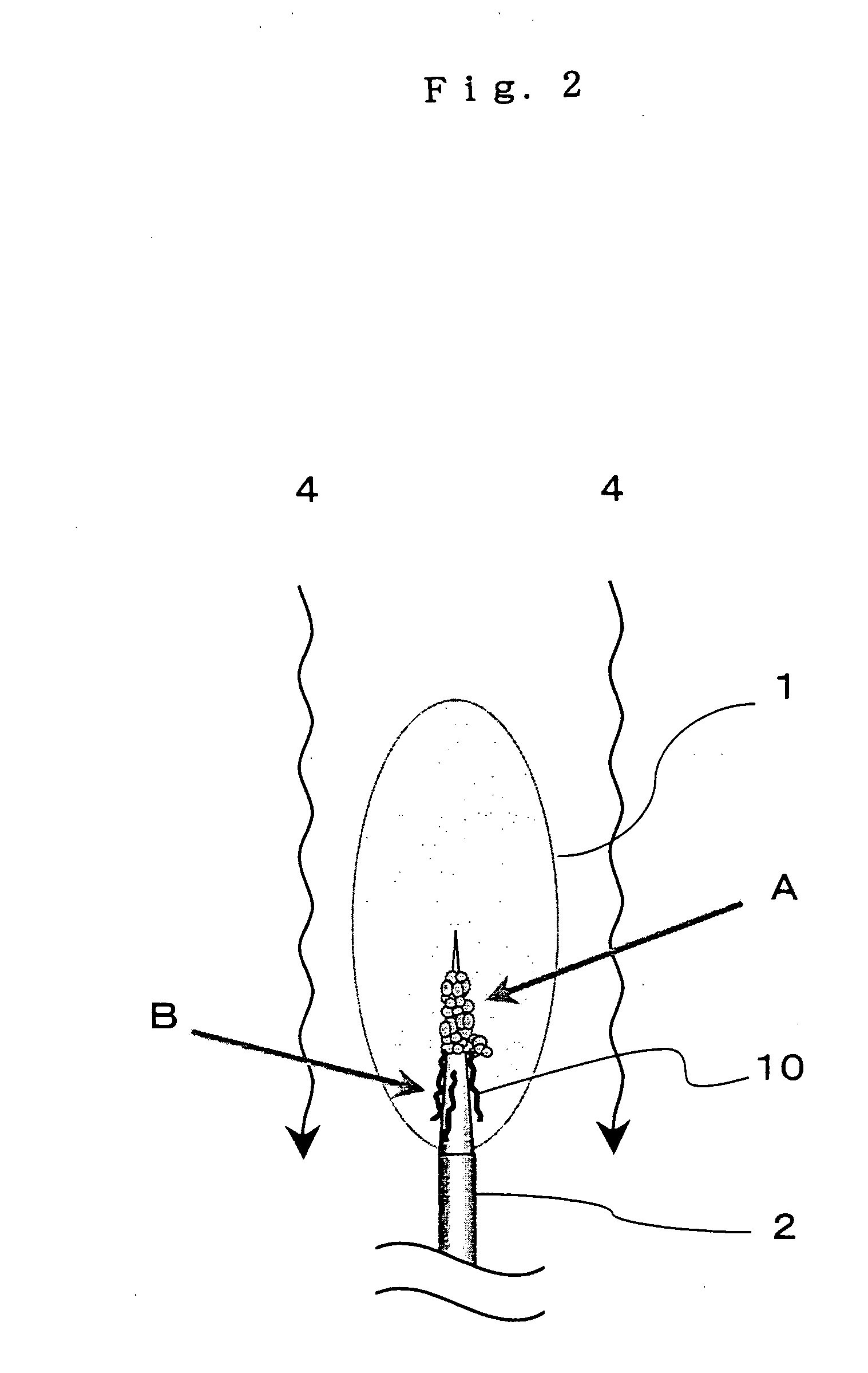
[0038] A acute tip, multi-wall carbon nanotube radial aggregate was produced by using a radio frequency plasma-generating device shown in FIG. 3. First, a hydrogen-added inert gas (4) was supplied to the inside of a quartz tube (5) and electric current of radio frequency (approximately 4 MHz) was applied to an induction coil (3) which was made of copper and wound around the outer periphery of the quartz tube (5), so that radio frequency plasma (1) was generated. Ar was used as the inert gas (4). Regarding the flow rate of Ar gas inside the quartz tube (5), the flow rate of the inner rotation gas which circulated inside the plasma (1) was set at 15 ml / min, the flow rate of the outer-radius gas which flowed straight at the outside of the plasma (1) was set at 15 ml / min, and the flow rate of the outer rotation gas which circulated outside the plasma (1) was set at 20 ml / min, so that the plasma flame (1) was maintained for a long time in a stable manner. Hydrogen was added to the Ar gas...
PUM
| Property | Measurement | Unit |
|---|---|---|
| Temperature | aaaaa | aaaaa |
| Length | aaaaa | aaaaa |
| Length | aaaaa | aaaaa |
Abstract
Description
Claims
Application Information