

Retardation plate, process for producing the same, and optical film
- Summary
- Abstract
- Description
- Claims
- Application Information
AI Technical Summary
Benefits of technology
Problems solved by technology
Method used
Image

Examples
example 1
Ethyl silicate 2% solution in ethyl acetate and isopropyl alcohol (trade name COLCOAT P, manufactured by COLCOAT Corporation) was coated as a sol solution for anchor coating onto a plastic film (manufactured by Toray Industries, Inc. thickness 50 micrometers) that include polyethylene terephthalate as a polymer material, by a photogravure roll coating method. Subsequently, obtained film was heated for 30 seconds at 130° C. to form a transparent vitreous polymer film (0.08 micrometers).
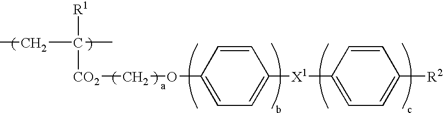
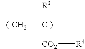
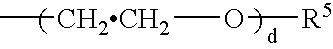
On the anchor coat layer provided on the film base material by a bar coating method, was coated a solution in which a side chain type liquid-crystal polymer 5 parts by weight represented by the above-mentioned chemical formula (the numbers in the formula represent mol % of monomer unit, shown in block format for convenience, a weight average molecular weight 5000), a photopolymerizable liquid-crystalline compound showing nematic liquid-crystal layer (manufactured by BASF A. G., PaliocolorLC242) 20 ...
example 2
Except for using a homeotropic liquid-crystal film having a thickness of 1.9 micrometers in Example 1, a same method as in Example 1 was used to produce a retardation plate. It had excellent homeotropic alignment. In the homeotropic liquid-crystal film, nx: 1.5349, ny: 1.5349, and nz: 1.6402.
example 3
Except for using a homeotropic liquid-crystal film having a thickness of 2.5 micrometers in Example 1, a same method as in Example 1 was used to producer a retardation plate. It had excellent homeotropic alignment. In the homeotropic liquid-crystal film, nx: 1.5334, ny: 1.5333, and nz: 1.6433.
PUM
| Property | Measurement | Unit |
|---|---|---|
| Thickness | aaaaa | aaaaa |
| Anisotropy | aaaaa | aaaaa |
| Optical properties | aaaaa | aaaaa |
Abstract
Description
Claims
Application Information