Modular cable termination plug

a technology of termination plugs and modules, applied in the direction of coupling contact members, coupling device connections, contact members penetrating/cutting insulation/cable strands, etc., can solve the problems of many communication problems in networks, crosstalk, and crosstalk that occurs when connectors are attached to twisted pair cables, etc., to achieve enhanced performance, reduce next variability, and be more versatile

Inactive Publication Date: 2005-02-17
PANDUIT
View PDF4 Cites 24 Cited by
  • Summary
  • Abstract
  • Description
  • Claims
  • Application Information

AI Technical Summary

Benefits of technology

[0007] The present invention overcomes the deficiencies of the prior art by providing an improved modular cable termination plug. The improved modular cable termination plug of the claimed invention utilizes mechanical features that will control the twist rate, un-twisted length, and position of individual conductors as well as twisted pairs of conductors within a cable and ensure repeatable placement of the conductors from the undisturbed cable to the point of termination. Accordingly, in comparison to the modular cable termination plugs available in the prior art, the claimed invention is more versatile and provides reduced NEXT variability and enhanced performance.

Problems solved by technology

When data is transmitted via an alternating current in a typical telecommunication application at such high frequencies, each individual conductor and each signal pair creates an electromagnetic field that can interfere with signals on adjacent conductors and adjacent signal pairs.
This undesirable coupling of electromagnetic energy between adjacent conductor pairs, referred to as crosstalk, causes many communications problems in networks.
In contrast, Near End Crosstalk (NEXT), the crosstalk that occurs when connectors are attached to twisted pair cables, is much more difficult to control.
As communication technology advances, however, and allows transmission at higher and higher frequencies, the modular plugs known in the prior art are no longer capable of maintaining NEXT levels within the ranges specified in widely accepted national performance standards.
In standard plug designs, however, pair-to-pair distortion, twist rate, and individual conductor positions are not strictly controlled.
This pinching deformation causes distortion and displacement of twisted pairs of conductors that in turn causes increased de-embedded NEXT variability.

Method used


Image

  • Modular cable termination plug
  • Modular cable termination plug
  • Modular cable termination plug

Examples


Embodiment Construction

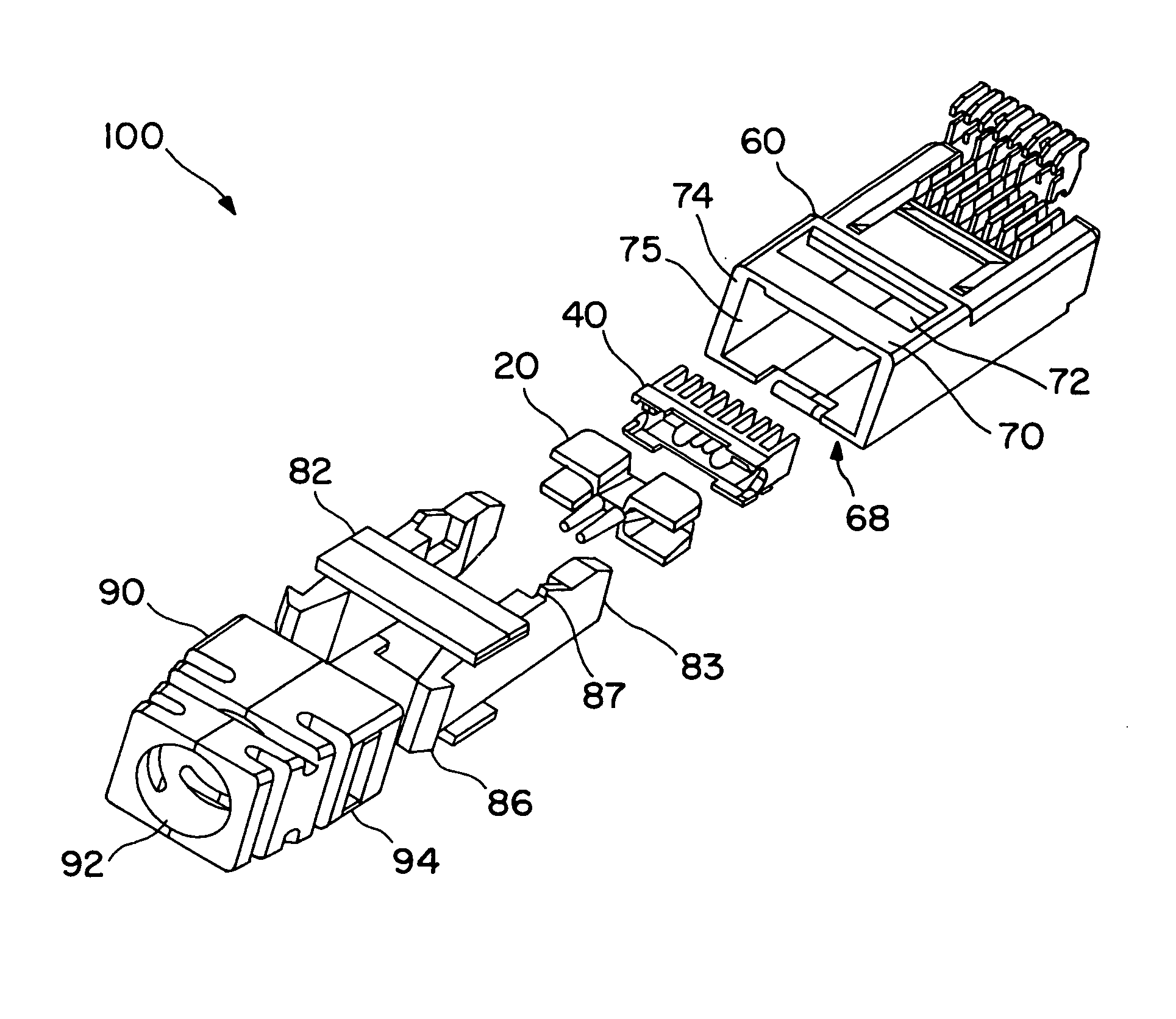
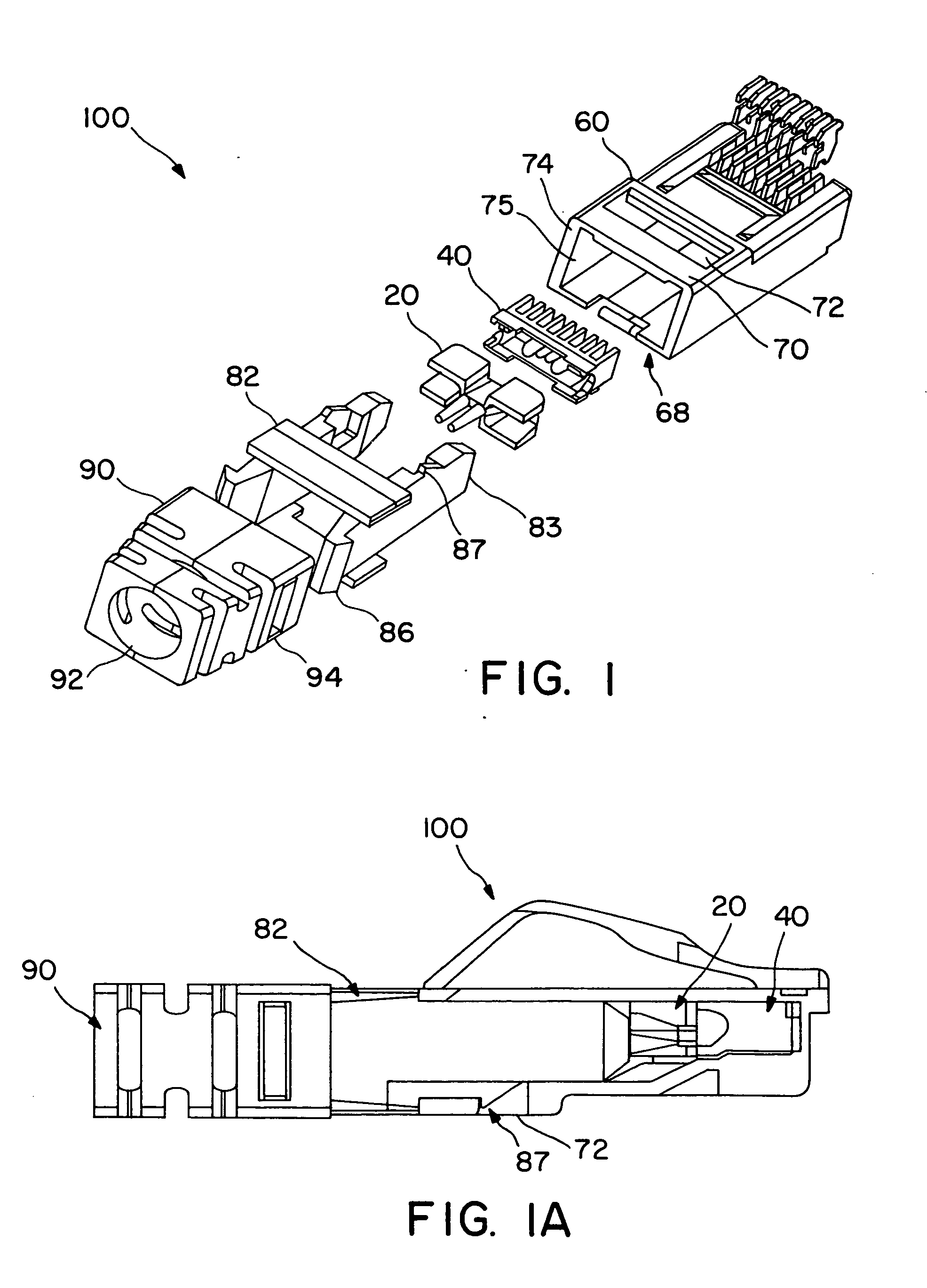
[0032] Referring now to the drawings, FIG. 1 shows an exploded perspective view of a modular plug assembly 100 in accordance with the claimed invention. In the preferred embodiment of the claimed invention, the plug assembly includes a strain relief boot 90, a strain relief collar 82, a conductor divider 20, a load bar 40, and a housing 60. The preferred modular plug 100 is depicted in an assembled state in the cross sectional view shown in FIG. 1A. As shown in FIG. 1A, the conductor divider 20 and the load bar 40 are designed to fit within the internal cavity 68 of the plug housing 60. The conductor divider 20 and the load bar 40 are secured in their proper location within the plug housing 60 by the walls 83 of the strain relief collar 82. In an assembled state, movement of the conductor divider 20, the load bar 40, and the strain relief collar 82 is preferably minimized through the use of an integrated snap. A horizontal latch tab 87 on the strain relief collar 82 engages against ...


PUM


Abstract

The invention is a modular cable termination plug having a conductor divider having an entrant barb and a plurality of divider channels, a load bar having a plurality of through holes and a plurality of slots, and a plurality of contact terminals. Additionally, the invention may include a housing, a strain relief collar and a strain relief boot.

Description

CROSS-REFERENCE TO RELATED APPLICATION [0001] This application is claiming priority to the previously filed U.S. provisional patent application Ser. No. 60 / 374,429, filed Apr. 21, 2003, entitled “Modular Cable Termination Plug,” incorporated herein by reference in its entirety.FIELD OF INVENTION [0002] The present invention relates generally to the field of modular plugs for terminating cables. More particularly, it relates to an improved plug for terminating communication cables having a plurality of twisted signal pairs of conductors and controlling the positions of the untwisted conductors in order to reduce near-end crosstalk. BACKGROUND OF THE INVENTION [0003] Communications networks generally transmit data at a high frequency over cables having a plurality of twisted signal pairs of conductors. For example, according to currently accepted performance standards, Category 5 products operate at frequencies up to 100 MHz and Category 6 products operate at frequencies up to 250 MHz...

Claims


Application Information

Patent Timeline
Patent Type & Authority Applications(United States)
IPC IPC(8): H01R13/58H01R4/24H01R13/648H01R24/00H01R33/76
CPCH01R4/2404H01R13/514H01R13/6463H01R24/64H01R13/5812
Inventor CAVENEY, JACK E.DOORHY, MICHAEL V.DYLKIEWICZ, DAVID A.GERMAN, JASON J.MARTINO, NICHOLAS G.
Owner PANDUIT
Why Eureka
Try Eureka