Microfluidic device for drug delivery

Active Publication Date: 2005-02-17
WISCONSIN ALUMNI RES FOUND
View PDF24 Cites 42 Cited by
  • Summary
  • Abstract
  • Description
  • Claims
  • Application Information

AI Technical Summary

Benefits of technology

[0007] Most people with diabetes administer their own insulin after learning the proper techniques for insulin preparation and injection. The goal of insulin administration is to give enough insulin to cover the amount of food (especially carbohydrates) that a person consumes so that blood glucose levels remain normal throughout the day and night. It can be appreciated that various factors such as the type of insulin used, the size of the person, the amount, type, and time that meals are eaten, and the activity and exercise patterns of the person effect the amount of insulin that is required by an individual. It takes a dedicated patient to continually monitor their blood glucose level and administer the repeated multiple injections required. Therefore, an auton

Problems solved by technology

As is known, the pharmaceutical industry has had limited success overcoming the challenges of delivering pharmaceuticals to patients.
However, the oral delivery of many pharmaceuticals is not possible because the pharmaceuticals are either too large or too electrically charged to pass through the small intestine to reach the bloodstream.
In addition, many pharmaceuticals that are unable to withstand the environment of the digestive tract or to penetrate the dermis need to be injected into the patient (e.g. insulin, proteins).
In people with diabetes, however, the

Method used


Image

  • Microfluidic device for drug delivery
  • Microfluidic device for drug delivery
  • Microfluidic device for drug delivery

Examples


Example

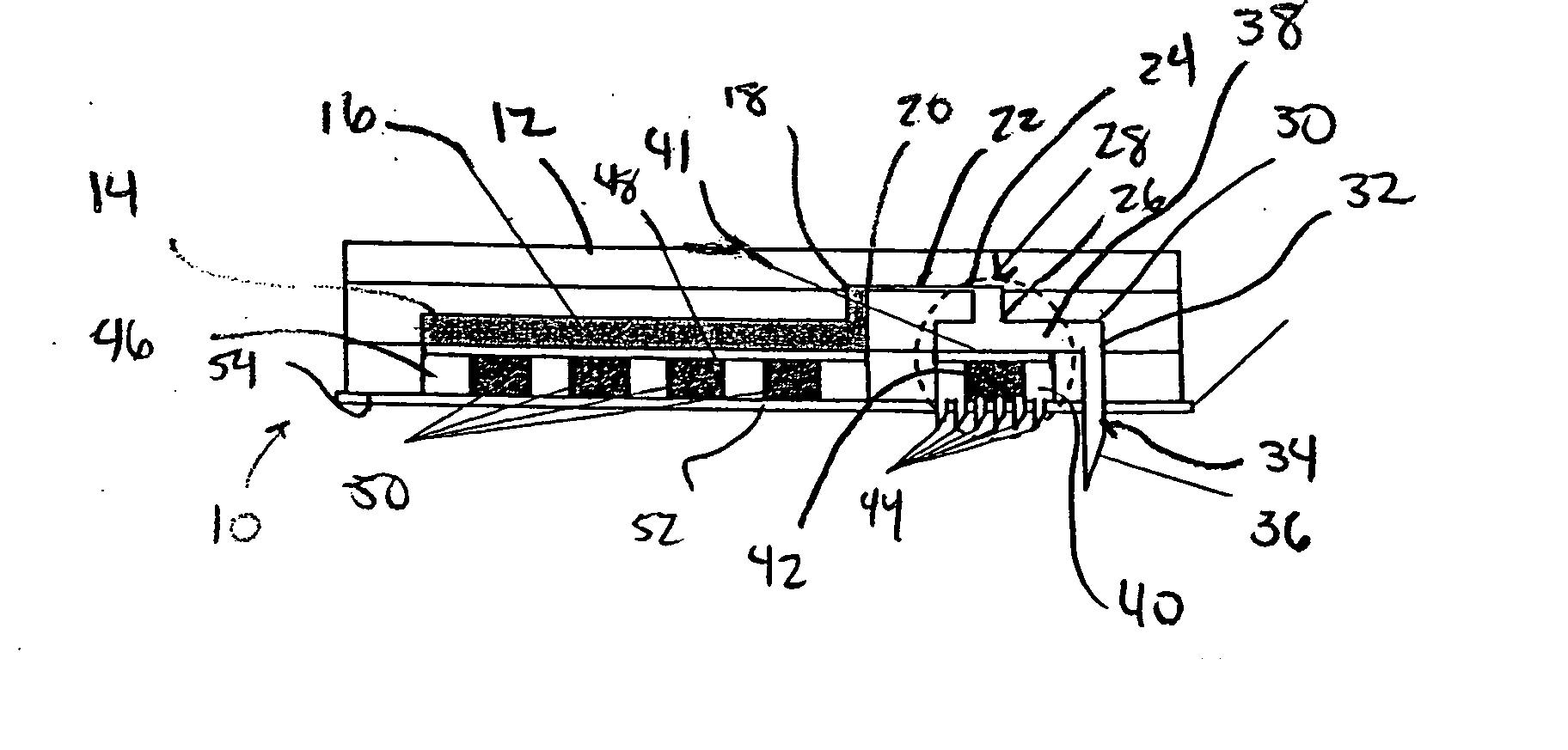
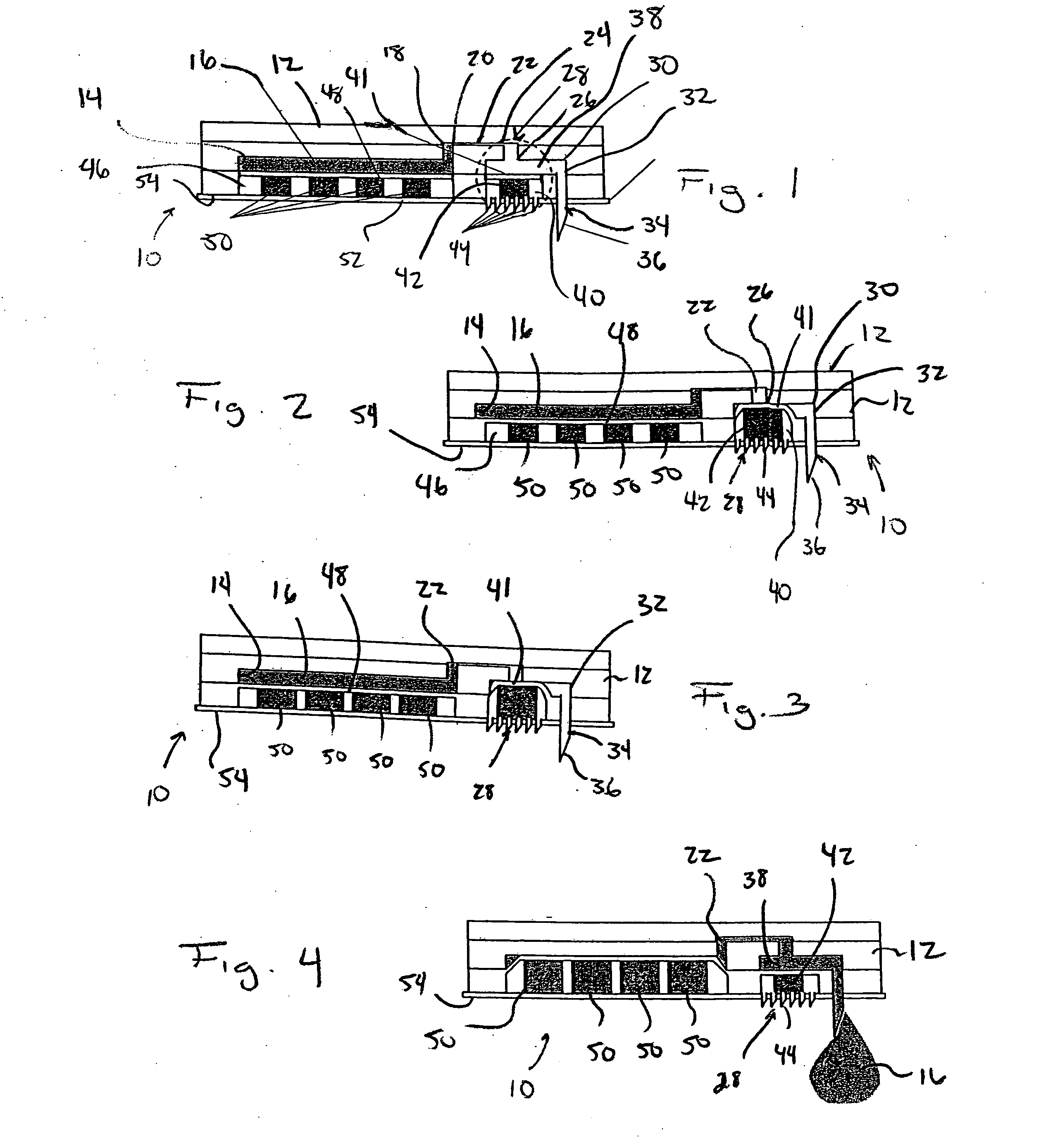
[0036] Referring to FIGS. 1-4, a microfluidic device in accordance with the present invention is generally designated by the reference numeral 10. Microfluidic device 10 includes body 12 formed from polydimethylsiloxane (PDMS) or the like in any conventional manner such as by compression micromolding or rapid prototyping. Body 12 defines reservoir 14 for the receiving and the storage of drug 16 therein. Reservoir 14 includes output 18 that communicates with input 20 of flow conduit 22. Output 24 of flow conduit 22 communicates with the input 26 of valve 28. Output 30 of valve 28 communicates with input 32 of outlet needle 34 that projects from body 12. Outlet needle 34 includes outlet end 36 that is injectable into an individual, as hereinafter described.

[0037] Valve 28 includes a valve chamber defined by drug flow portion 38 and trigger receiving portion 40. Drug flow portion 38 and trigger receiving portion 40 of the valve chamber within valve 28 are isolated from each other by f...


PUM


Abstract

A microfluidic device is provided for delivering a drug to an individual. The microfluidic device includes a body that defines a reservoir for receiving the drug therein. A valve interconnects the reservoir to an output needle that is insertable into the skin of an individual. A pressure source urges the drug from the reservoir toward the needle. The valve is movable between a closed position preventing the flow of the drug from the reservoir to the output needle and an open position allowing for the flow of the drug from the reservoir to the output needle in response to a predetermined condition in the physiological fluids of the individual.

Description

CROSS REFERENCE TO RELATED APPLICATION [0001] This application is a continuation application of present co-pending U.S. application Ser. No. 10 / 640,345, filed on Aug. 13, 2003, and entitled “Microfluidic Device For Drug Delivery,” the entirety of which is incorporated herein by reference.REFERENCE TO GOVERNMENT GRANT [0002] This invention was made with United States government support awarded by the following agencies: NASA NAG8-1672. The United States has certain rights in this invention.FIELD OF THE INVENTION [0003] This invention relates generally to microfluidic devices, and in particular, to a microfluidic device for delivering a steady infusion of a drug to an individual. BACKGROUND AND SUMMARY OF THE INVENTION [0004] As is known, the pharmaceutical industry has had limited success overcoming the challenges of delivering pharmaceuticals to patients. The oral ingestion of pharmaceuticals is considered the safest, most convenient and most economical method of drug administration...

Claims


Application Information

Patent Timeline
IPC IPC(8): A61M5/14A61M5/142A61M5/145A61M5/168A61M31/00
CPCA61M5/141A61M5/14248A61M2005/1726A61M5/16881A61M5/14586
Inventor BEEBE, DAVID J.MACDONALD, MICHAEL J.EDDINGTON, DAVID T.MENSING, GLENNYS A.
Owner WISCONSIN ALUMNI RES FOUND
Why Eureka
Try Eureka