Intake Air Systems and Components

Active Publication Date: 2019-11-28
AUTO IP LLC
View PDF0 Cites 6 Cited by
  • Summary
  • Abstract
  • Description
  • Claims
  • Application Information

AI Technical Summary

Benefits of technology

The present invention is a system of inter-cooperative intake air components that can be easily assembled and swapped to create different engine performance characteristics. The system includes an intercooler that is small and versatile, allowing for the use of different air inlets and outlets depending on the engine design. This compact design also allows for the option of multiple intercoolers, which can be placed in a limited space in the engine or even attached to the engine itself, to increase cooling capacity and further improve engine performance.

Problems solved by technology

Whether supercharging or turbocharging is used, compressing the intake air can cause the air to rise in temperature.
While desirably reducing intake air temperature, placement of a heat exchanger can be a challenge in the limited space of a vehicle engine compartment, as can be the routing of the necessary air ducts and cooling fluid circuits.
Thus the introduction of a heat exchanger, sometimes referred to as an intercooler, can result in complex plumbing arrangements that can make service difficult, be costly and cause frictional losses.

Method used


Image

  • Intake Air Systems and Components
  • Intake Air Systems and Components
  • Intake Air Systems and Components

Examples


Embodiment Construction

[0055]The components of the present invention are preferably utilized in conjunction with V-style reciprocating internal combustion engines; i.e., engines having two cylinder banks of at least two cylinders each, each bank arranged in a row inclined from the vertical so as to form a “V”, including V-4 engines, V-6 engines, V-8 engines, V-12 engines, V-16 engines, etc.

[0056]The components of the present invention can be selected and arranged to provide an upward flow (i.e., updraft) air intake configuration, or a downward flow (i.e., downdraft) air intake configuration. In an upward flow / updraft air intake configuration, intake air that has been compressed (preferably by one or more turbochargers) is drawn into the intake system upwardly, away from the engine, through one or more intercoolers 300 and then redirected to an engine intake manifold, for distribution to the cylinders. In a downward flow / downdraft air intake configuration, ambient or compressed intake air is drawn into the...


PUM


Abstract

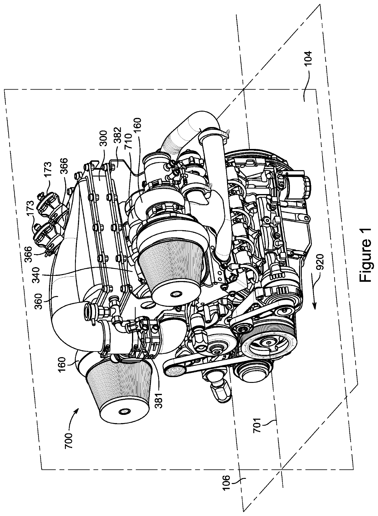
Intake air systems featuring novel intercooler and air distribution system components. The intercooler component has a rectangular 
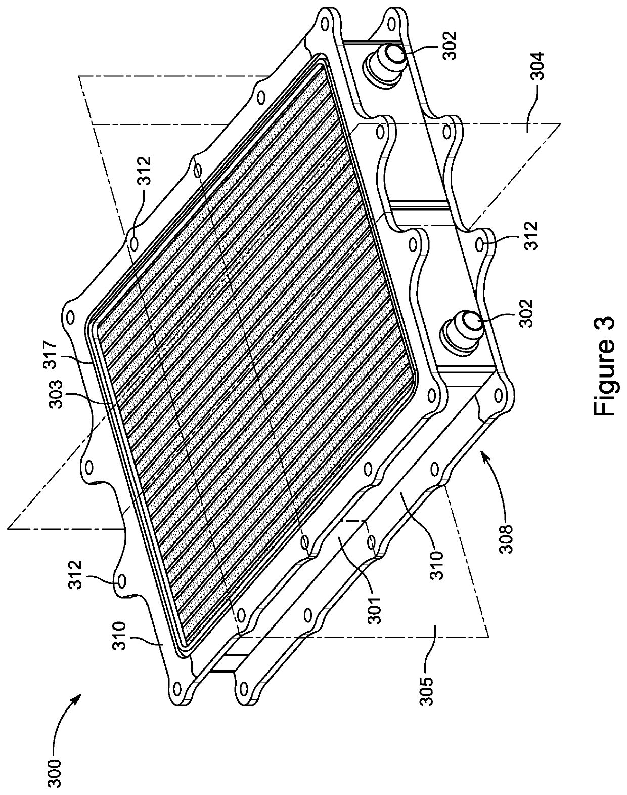
heat exchanger core for cooling air with a liquid, and the heat exchanger core has a first face for entry of uncooled air and a second opposing face for exit of cooled air. A first rectangular intercooler mounting flange structure is secured to the periphery of the first face and a second intercooler rectangular mounting flange structure is secured to the periphery of the second face. The first rectangular intercooler mounting flange structure and the second rectangular intercooler mounting flange structure are of approximately the same size and geometry, and the first rectangular intercooler mounting flange structure and the second rectangular intercooler mounting flange structure have substantially identical plural spaced-apart symmetrically distributed bolt apertures. The first rectangular intercooler mounting flange structure comprises a first L-shaped core mounting flange and a second L-shaped core mounting flange, the second rectangular intercooler mounting flange structure comprises a third L-shaped core mounting flange and a fourth L-shaped core mounting flange, and the first L-shaped core mounting flange, the second L-shaped mounting flange, the third L-shaped mounting flange and the fourth L-shaped core mounting flange all have approximately the same size and geometry. The air distribution system component has an air distribution tray adapted for mounting to the engine between the first and second row of cylinders, where the air distribution tray has a planar perimeter defining a horizontal plane and plural outlet ports, the plural outlet ports are disposed in an alternating staggered relationship about a longitudinal plane perpendicular to the horizontal plane, each of the plural outlet ports is adapted for connection to a respective air intake port of the cylinders of the internal combustion engine, and the air distribution tray is configured so that the planar perimeter of the air distribution tray is above both the engine and the outlet ports when the air distribution system is mounted to the engine and the plural outlet ports are connected to the air intake ports of the cylinders. The air distribution tray includes plural distribution channels configured to be below the planar perimeter when the air distribution tray is mounted to the engine, where each distribution channel generally is concavely curved about a longitudinal axis located in the longitudinal plane and is bounded by a first end and a second end, with the first end of each of the plural distribution channels coupled to a respective one of the plural outlet ports and the second end being longitudinally offset from the first end, and with the distribution channel shaped to trace approximately a serpentine path in the horizontal plane along its length between the first end and the second end. The air distribution system additionally includes an air passage closure tray fitted in a mating relationship with the air distribution tray, where the air passage closure tray includes plural closure channels, each of which is equal to or shorter in length than, and concavely curved and shaped to engage in a mating relationship with, a respective one of the plural distribution channels, to form plural concavely curved closed air conduits that are configured to be below the planar perimeter when the air distribution system is mounted to the engine. Each of the plural closure channels has a third end terminating in a conduit inlet port and a fourth end communicating with a respective outlet port of the air distribution tray, and each of the plural closed air conduits is adapted to draw air from a common air region above the conduit inlet ports when the air distribution system is mounted to the engine, with adjacent pairs of the plural closed air conduits configured to provide alternating opposing air flow paths from their respective conduit inlet ports to the respective outlet ports with which they communicate.

Description

CROSS-REFERENCES TO RELATED APPLICATIONS[0001]This application is a continuation-in-part application of U.S. patent application Ser. No. 16 / 168,984, filed Oct. 24, 2018, which claims the benefit of U.S. Provisional Application No. 62 / 687,461, filed Jun. 20, 2018, U.S. Provisional Application No. 62 / 697,072, filed Jul. 12, 2018, U.S. Provisional Application No. 62 / 678,460, filed May 31, 2018, U.S. Provisional Application No. 62 / 616,601, filed Jan. 12, 2018, U.S. Provisional Application No. 62 / 598,045, filed Dec. 13, 2017, U.S. Provisional Application No. 62 / 577,965, filed Oct. 27, 2017, and U.S. Provisional Application No. 62 / 577,423, filed Oct. 26, 2017.BACKGROUND OF THE INVENTIONField of the Invention[0002]This invention relates to components, and systems arranged from such components, for introducing outside air to an internal combustion engine.Description of the Related Art[0003]The guidance and conditioning of ambient air from the atmosphere to the combustion regions or chambers...

Claims


Application Information

Patent Timeline
IPC IPC(8): F02M35/10F02M35/104F02M35/02F02B39/04
CPCF02B39/04F02M35/0201F02M35/10039F02M35/10354F02M35/104F02B29/0462F02M35/116Y02T10/12
Inventor TIRAMANI, PAOLODENMAN, KYLE
Owner AUTO IP LLC
Why Eureka
Try Eureka