Blower

Active Publication Date: 2005-02-24
ANDREAS STIHL AG & CO KG
View PDF8 Cites 14 Cited by
  • Summary
  • Abstract
  • Description
  • Claims
  • Application Information

AI Technical Summary

Benefits of technology

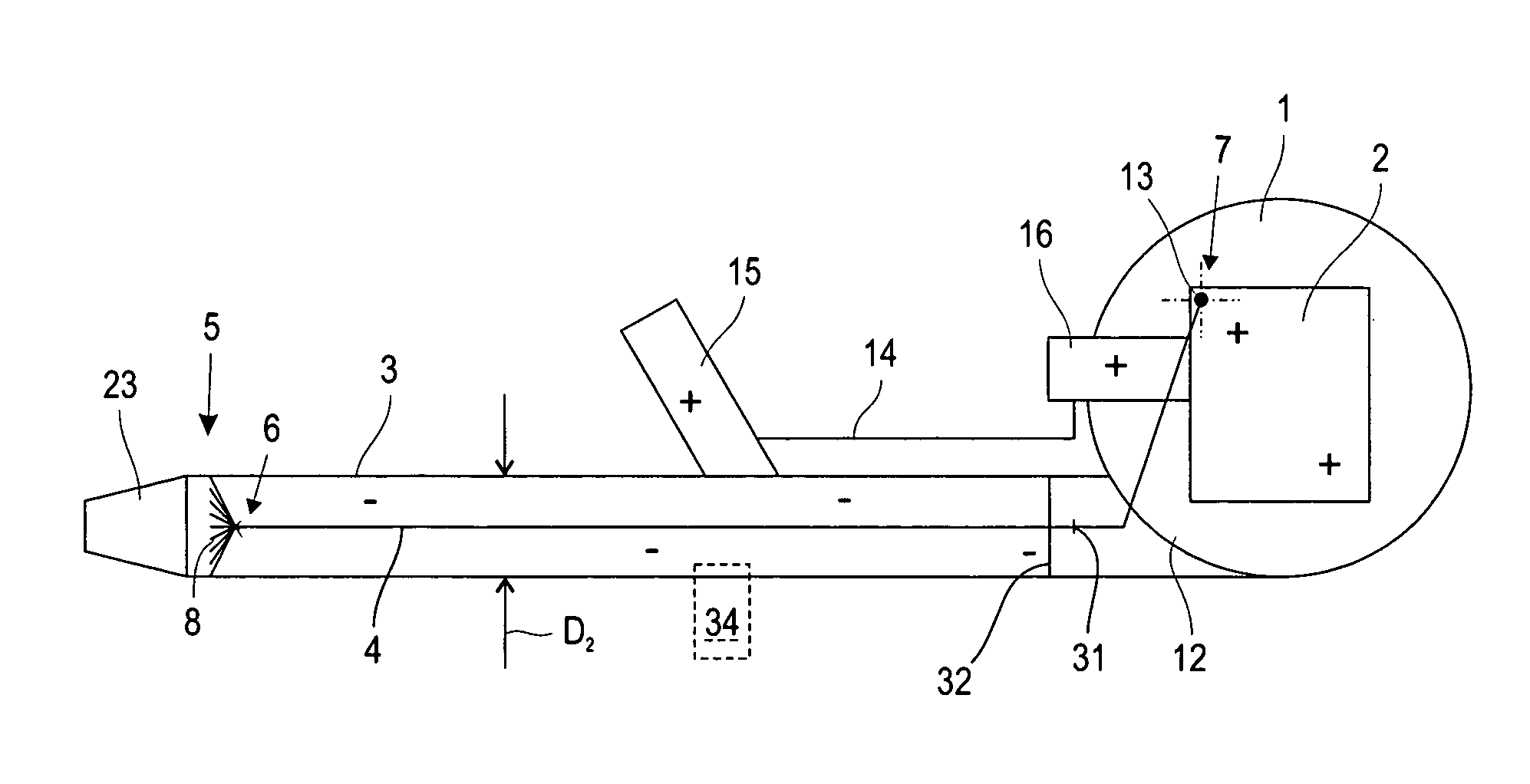
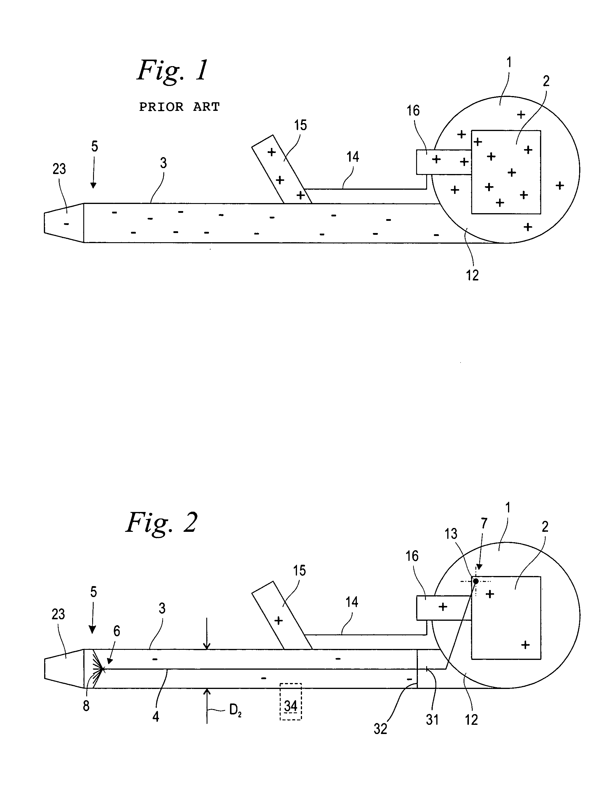
[0028] Pursuant to an advantageous further development, the potential compensation conductor is free of electrical insulation at least nearly over its entire length. In this connection, the potential compensation conductor can, directly at the location where it occurs, compensate for the electrostatic charge that forms over the travel length of the air stream. The formation of individual regions having no potential compensation is avoided.
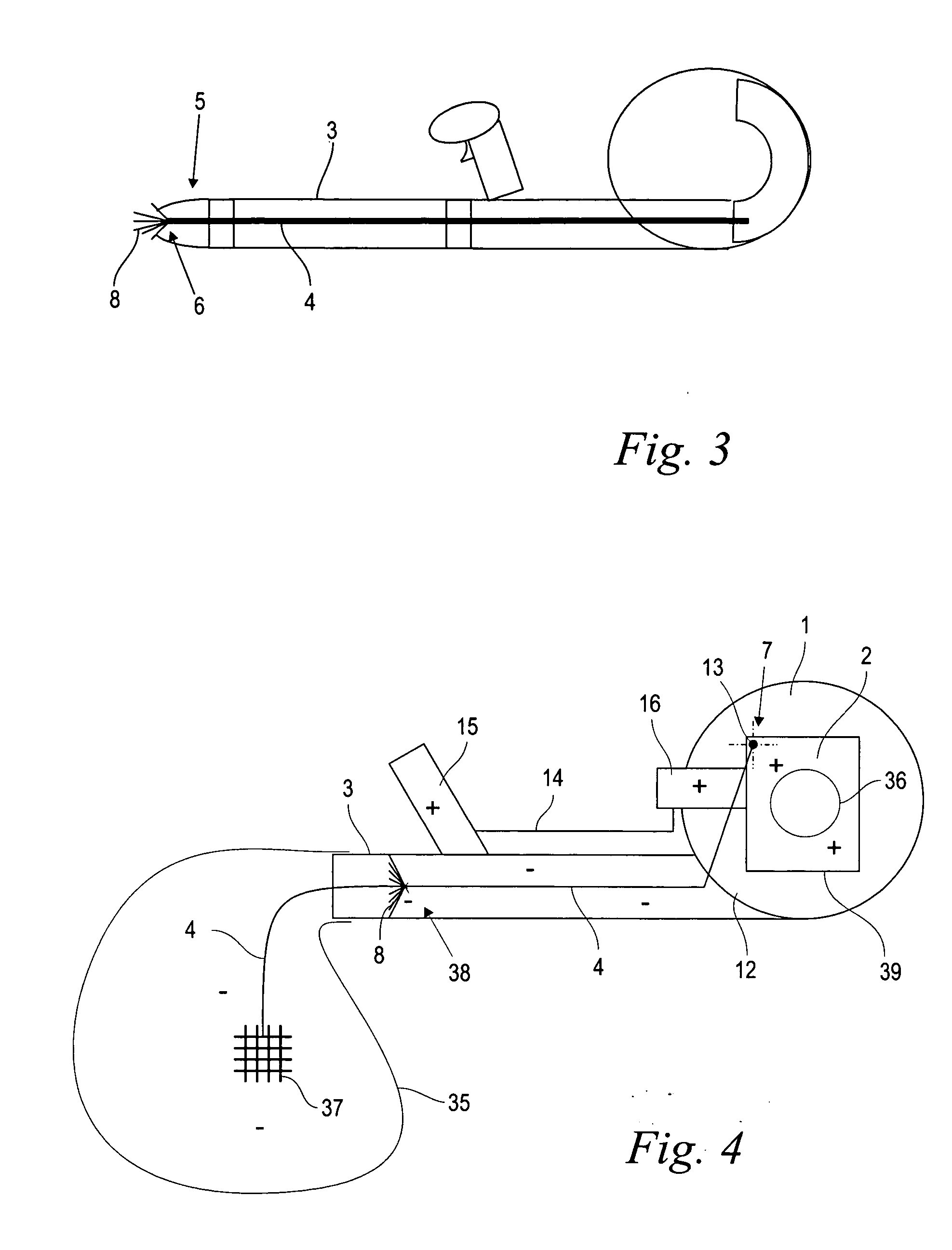
[0029] An embodiment of the potential compensation conductor as a flexible wire structure, and in particular as a stainless steel wire, has shown to be expedient. A reliable potential compensation with little mechanical sensitivity against abrasive effects from the dust particles or the like carried along in the air stream results.
[0030] Pursuant to an advantageous further development, in the region of the end that is remote from the motor individual strands of the steel wire are untwisted and are bent radially outwardly to form the spider. The geometrically complex structure of potential compensation conductor and spider can, in a surprisingly easy manner, be monolithically produced from a twisted steel wire with little manufacturing expense.
[0031] The steel wire is advantageously embodied in such a way that under the effect of a cut, its strands automatically untwist. Such a steel wire is also designated as not being resistant to sectioning, whereby upon cutting the potential compensation conductor to length from a continuous steel wire material, the individual strands automatically un

Problems solved by technology

At appropriate atmospheric conditions, and when dirt or dust particle laden ambient air is drawn in, in particular due to friction between the particles as well as with the fa

Method used


Image

  • Blower
  • Blower
  • Blower

Examples


Example

[0036] Referring now to the drawings in detail, the schematic block diagram of FIG. 1 shows the essential components of a manually guided blower according to the state of the art. The blower has a blower fan 1, which is driven by a motor 2. In the illustrated embodiment, the motor 2 is an internal combustion engine having an indicated carburetor 16. An electric motor or the like can also be provided. The blower fan 1 is provided with a discharge bend or knee 2, which is adjoined by a blower tube 3 that continues from the blower fan 1. The blower tube 3 has a free end 5, on which is disposed a nozzle 23. An air stream is conveyed out of the blower fan 1 through the discharge knee 12 and from there is conveyed through the blower tube 3 and the nozzle 23.

[0037] Mounted on the outer side of the blower tube 3 is a handle or hand grip 15 having control elements for the motor 2. A gas lever or cable 14, for example, leads from the control elements on the hand grip 15 to the carburetor 16....


PUM


Abstract

A blower is provided, and comprises a blower fan, a motor for driving the fan, a blower tube that extends from the fan, and a potential compensation conductor that extends within the blower tube and is connected with the motor in an electrically conductive manner.

Description

BACKGROUND OF THE INVENTION [0001] The present invention relates to a blower having a blower fan, a motor for driving the fan, and a blower tube that extends from the fan. [0002] With manually guided blowers, by means of a motor-operated fan an air stream is produced that by means of a blower tube that extends from the fan is guided to the desired application. Such blowers are carried, for example, on the back of an operator, and are manually guided, being used for blowing fallen leaves into a pile. The blower can also be used as a spray device, whereby an agent or material that is to be sprayed, such as plant protection material or granulate, is introduced into the blower tube. By means of a venturi device and a collection bag, such a blower can also be used as a nut collector or the like. The housing of the blower fan, the fan wheel, and in particular the blower tube are made of polymeric material, whereby the polymeric material acts as an electrical insulator relative to the driv...

Claims


Application Information

Patent Timeline
IPC IPC(8): A47L5/14A47L9/28F04D27/02H05F3/02
CPCA47L5/14A47L9/2842A01G1/125H05F3/02F04D27/008A47L9/2889A01G20/47
Inventor JOOS, STEFFEN
Owner ANDREAS STIHL AG & CO KG
Why Eureka
Try Eureka