The
nitrogen oxide NOx (NO and NO2) that is discharged from various
combustion devices is not only harmful to the
human body, but is also a cause of
acid rain and the
greenhouse effect, and as a result has become subject to official emission controls in industrialized nations.
The technical aspect to this is that it is far more difficult to form a pre-mixture with a high degree of homogeneity when using
liquid fuel than when using gaseous fuel.
If, as a result of this auto-ignition, a
flame is formed within the premixing tube and held within the interior of the tube, the premixing tube, fuel
atomizer nozzle, and so on are damaged by burning.
When fuel particle dispersal is insufficient, the fuel concentration distribution remains uneven over the cross section of the premixing tube outlet even if the fuel particles are completely vaporized.
It is particularly difficult to avoid this unevenness when the
diameter of the premixing tube is large.
However, a problem which arises when forming a swirl within the premixing tube is that regions with a low velocity are typically formed in the vicinity of the central axis such that when the swirl is strong, a back flow is formed.
This increases the likelihood of so-called backfiring, in which a
flame runs up through these regions within the premixing tube from the
combustion chamber.
If, in a premixing tube taking the form of a venturi tube, the air
stream is caused to swirl in order to promote dispersion of the fuel particles and mixing of the
fuel vapor and air, a back flow region is formed on the central axis of the enlarged portion, increasing the likelihood of backfiring.
This problem can be solved by bundling together a large number of prevaporizing tubes with small passage cross sections, but this solution leads to further problems such as complication of the
fuel supply system, weight increases, and so on.
Since fuel also exists in this part, backfiring is likely to occur.
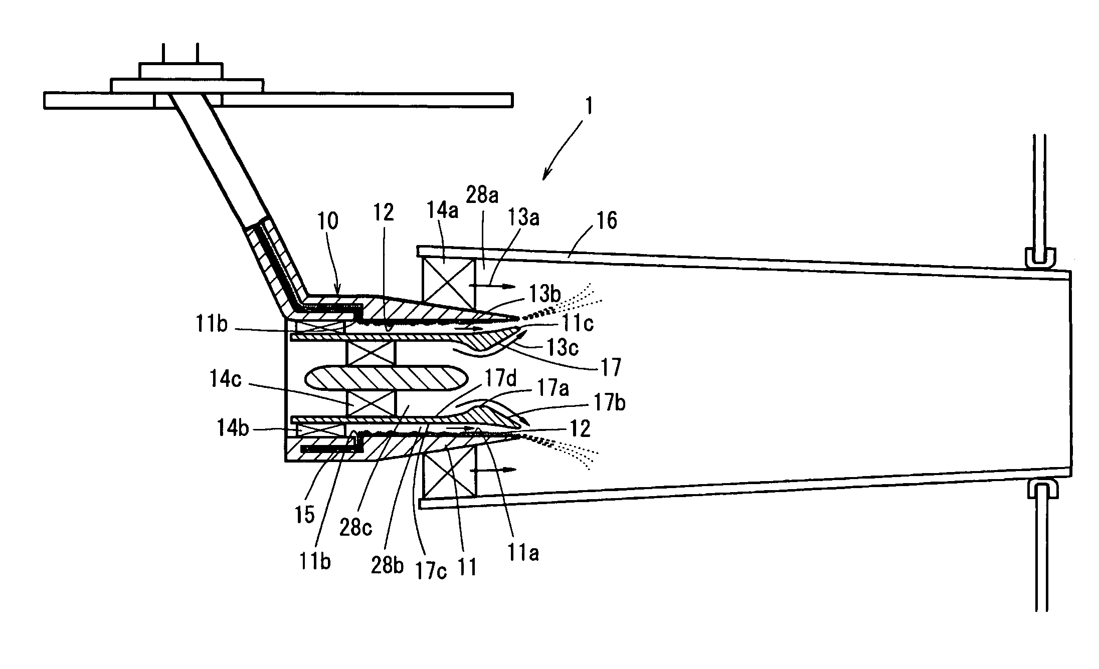
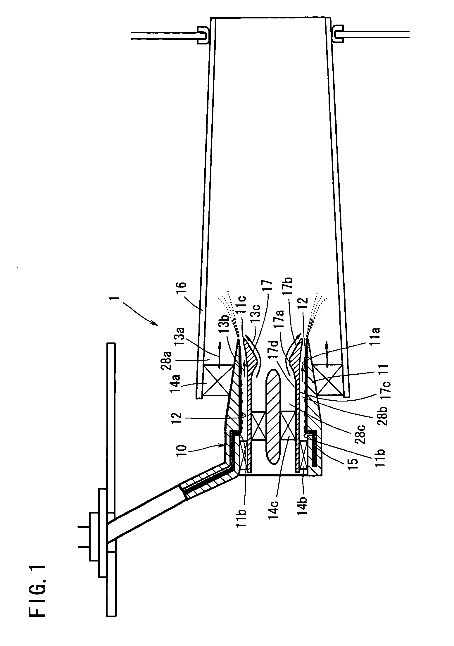
The problem with this type of fuel / air premixer for a gas turbine
combustor is that a
flame is formed at the outlet of the premixing tube, and hence the tip end portion of the central body is heated excessively by the flame and
radiation from the flame.
If the tip end of the central body is positioned upstream of the premixing tube outlet in an effort to suppress such excessive heat, the end of the back flow region, which had been positioned downstream of the premixing tube outlet, moves within the premixing tube, and hence the vicinity of the premixing tube outlet may be heated excessively.
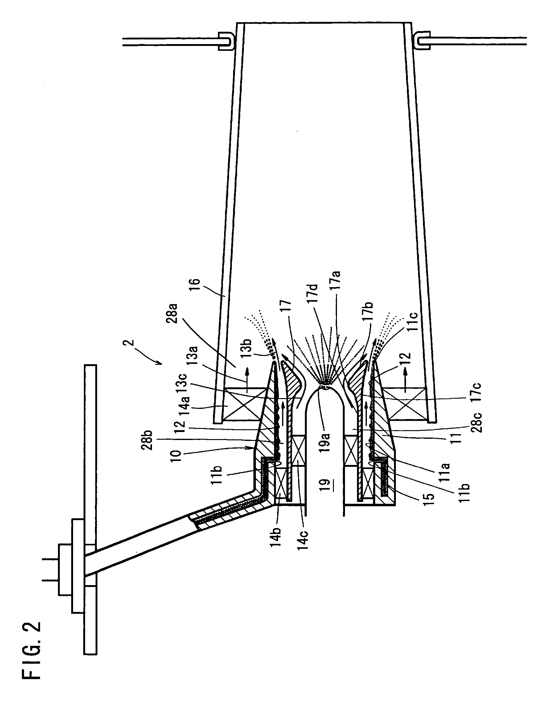
Moreover, the very existence of the central body wastes space and increases weight, and since the central body is supported by vanes of the air swirler attached to the inlet portion of the premixing tube, thus forming a so-called
cantilever structure, there is a danger of the central body falling off due to combustion vibration or the like.

