Method and apparatus for providing a layer of compressive residual stress in the surface of a part

a residual stress and surface technology, applied in heat treatment apparatus, heat treatment process control, manufacturing tools, etc., can solve the problems of more rapid fatigue or stress corrosion failure, and high degree of surface deformation and cold working, so as to reduce cold working and processing time

Active Publication Date: 2005-02-24
SURFACE TECH HLDG
View PDF8 Cites 22 Cited by
  • Summary
  • Abstract
  • Description
  • Claims
  • Application Information

AI Technical Summary

Benefits of technology

The present invention is a new and novel method and apparatus of providing a layer of compressive residual stress in the surface of a part and, more particularly, provides an improved and novel method and apparatus of shot peening that induces a desired amount of residual compressive stress within the surface of the part that is less susceptible to thermal and mech

Problems solved by technology

Residual stresses, such as tensile residual stresses, add to the applied stresses imposed on a part in service and can lead to more rapid fatigue or stress corrosion failure.
Unfortunately, it has been shown that such conventional shot peening induces a high degree of surface deformation and cold working which increases with increasing shot peening

Method used


Image

  • Method and apparatus for providing a layer of compressive residual stress in the surface of a part
  • Method and apparatus for providing a layer of compressive residual stress in the surface of a part
  • Method and apparatus for providing a layer of compressive residual stress in the surface of a part

Examples


example 1

RESULTS

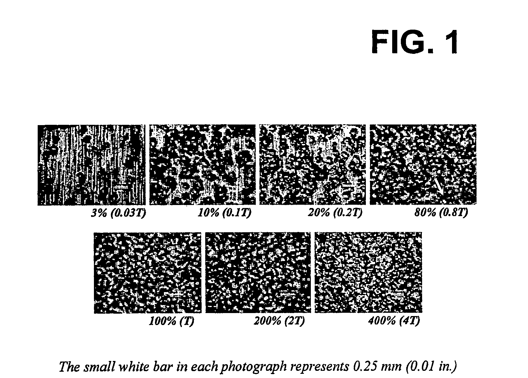
Referring to FIG. 1, representative metal surfaces are shown that have been peened, as described above, to various coverages. Defined coverage was based upon the time ratio to achieve 100% dimpling of the surface area. It should be apparent to those skilled in the art that the percent of area covered at 80% (0.8T) coverage approached that of 100% (1T) coverage. As shown, the arrow in the photograph for 0.8T identifies a relatively small undimpled area visible when viewed optically at 20× magnification. The undimpled areas of the specimens peened for less than 0.8T are obvious in appearance. The overall appearance of surfaces peened for times, 2T and 4T, did not change relative to that peened for time T.

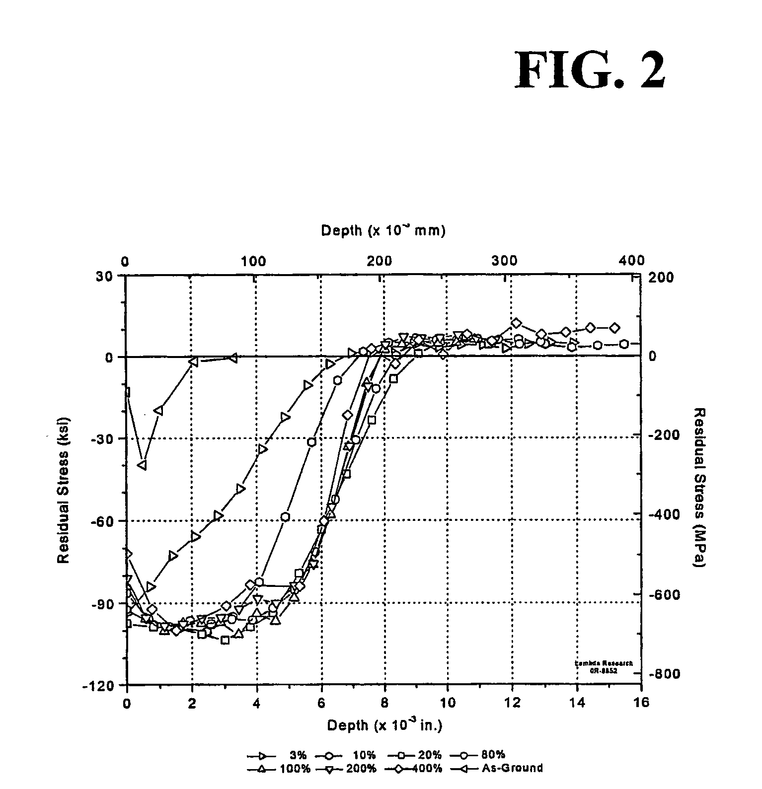
FIG. 2 illustrates the residual stress-depth distributions that were obtained in the example for the various coverage levels, including the distribution for the as ground surface before peening. Except at the lowest coverage level, 3% (0.03T), classical shot peening distribut...

example 2

RESULTS

FIG. 8 illustrates, the residual stress-depth distributions that were obtained in the IN718 example for the various coverage levels. As shown with Example 1, except at the lowest coverage level, 5% (0.03T), classical shot peening distributions resulted, whereby residual compressive stress magnitudes reached a subsurface maximum and decreased gradually until small tensile stresses occurred at greater depths. For 5% coverage levels, the maximum compression is shown to have occurred at the upper surface. As in Example 1, since x-ray diffraction results provide an average stress over mostly un-impacted material at the 5% coverage level, it would be apparent to one skilled in the art that even the regions between impacts are in compression. The residual stress distributions for coverage levels less than about 10% (0.1T) exhibited systematic changes with coverage, whereby increasing coverage in this range resulted in increasing compressive stress magnitude at given subsurface depth...


PUM

PropertyMeasurementUnit
Fractionaaaaaaaaaa
Fractionaaaaaaaaaa
Fractionaaaaaaaaaa

Abstract

The shot peening method and apparatus (FIG. 13) of the present invention utilizes control of the shot peening coverage to provide higher surface compression and comparable depth of compression to conventional 100% coverage peening but with reduced cold working providing improved thermal stability and reduction in shot peening time and cost. A preferred embodiment of this invention employs x-ray diffraction (FIG. 13) residual stress and percent cold work determinated by line broadening to establish the optimal degree of coverage for a given material and shot peening intensity.

Description

TECHNICAL FIELD This invention relates to a method and an apparatus of providing a layer of compressive residual stress in the surface of a part and, more particularly, to an improved and novel method and apparatus of shot peening. BACKGROUND Surface residual stresses are widely known to have a major effect upon fatigue and stress corrosion performance of metallic parts. Residual stresses, such as tensile residual stresses, add to the applied stresses imposed on a part in service and can lead to more rapid fatigue or stress corrosion failure. Compressive residual stresses have been shown to have the effect of countering applied tension and have been used to generally improve the life of a part by reducing its overall stress state and by retarding fatigue and stress corrosion crack initiation and growth. A variety of surface enhancement methods, such as shot peening, gravity peening, laser shocking, deep rolling, low plasticity burnishing, split sleeve cold expansion and similar me...

Claims


Application Information

Patent Timeline
IPC IPC(8): C21D7/06C21D11/00
CPCC21D7/06Y10T29/479C21D11/00
Inventor PREVEY, PAUL S.CAMMETT, JOHN T.
Owner SURFACE TECH HLDG
Why Eureka
Try Eureka