Electromagnetic wave shielding window, manufacturing apparatus having the same, transport system having the same, building construction having the same, and electromagnetic wave shielding method

a technology of electromagnetic shielding and electromagnetic wave, which is applied in the direction of transportation and packaging, chemistry apparatus and processes, and other domestic objects, can solve the problems of increasing the occurrence of unwanted electromagnetic energy, increasing the risk of malfunction, so as to save construction costs, reliable shielding effect, and the effect of increasing the beauty of appearan

Inactive Publication Date: 2005-02-24
PANASONIC CORP
View PDF5 Cites 27 Cited by
  • Summary
  • Abstract
  • Description
  • Claims
  • Application Information

AI Technical Summary

Benefits of technology

[0014] The invention was devised in view of the foregoing situations, and therefore, has an object to provide an electromagnetic wave shielding method and an electromagnetic wave shielding window capable of bringing a conductive shielding member into conduction to the outside without the need of a connecting structure, and a manufacturing apparatus, a transport system, and a building construction each having the electromagnetic wave shielding window, so that man-hours needed for manufacturing and the manufacturing cost can be reduced while a stable electromagnetic wave shielding effect is ensured over a long period.

Problems solved by technology

Recently, emission of unwanted electromagnetic energy has been on the increase with increasing use of electric energy, and adverse effects of such emission to environments are being concerned.
The environmental issues posed by an electromagnetic wave include: mutual interference of channels and ghosts of a broadcast wave in regard to wireless communications; the safety of a robot system in regard to a manufacturing apparatus; reliability of a communications network in regard to information processing, etc.
In regard to a transport system, electronic control is increasingly involved in the operation control in recent years, and fear for a malfunction is becoming a key issue.
In regard to a building construction, a building construction itself has now become a huge antenna as a computer network is provided throughout the construction like the one called today's intelligent building, and because electromagnetic energy is emitted untreated to local residents, influences of electromagnetic wave energy to the bio-ecological system is also becoming a key issue.
The structure of the conventional electromagnetic wave shielding windows described above, however, has a problem that it becomes a complicated connecting structure due to the need to connect the conductive shielding member to the window frame or the like at the outside.
Moreover, precise and careful assembly is required for any of the electromagnetic wave shielding windows, because in the event that a local void is caused during the assembly of the electromagnetic wave shielding window, an electromagnetic wave leaks through the void and the shielding ability can no longer be ensured.
Hence, the conventional electromagnetic wave shielding window demands an elaborate connecting work to connect the conductive shielding member and an outside grounding or the like, which poses a problem that not only man-hours needed for the work, but also the manufacturing cost is increased.
Also, in a case where the conductive shielding member is connected to the outside grounding or the like through an adhesive agent, the connecting portion may deteriorate with time due to degradation, such as oxidation and corrosion, which poses a problem that a stable electromagnetic wave shielding effect cannot be achieved over a long period.

Method used


Image

  • Electromagnetic wave shielding window, manufacturing apparatus having the same, transport system having the same, building construction having the same, and electromagnetic wave shielding method
  • Electromagnetic wave shielding window, manufacturing apparatus having the same, transport system having the same, building construction having the same, and electromagnetic wave shielding method
  • Electromagnetic wave shielding window, manufacturing apparatus having the same, transport system having the same, building construction having the same, and electromagnetic wave shielding method

Examples


first embodiment

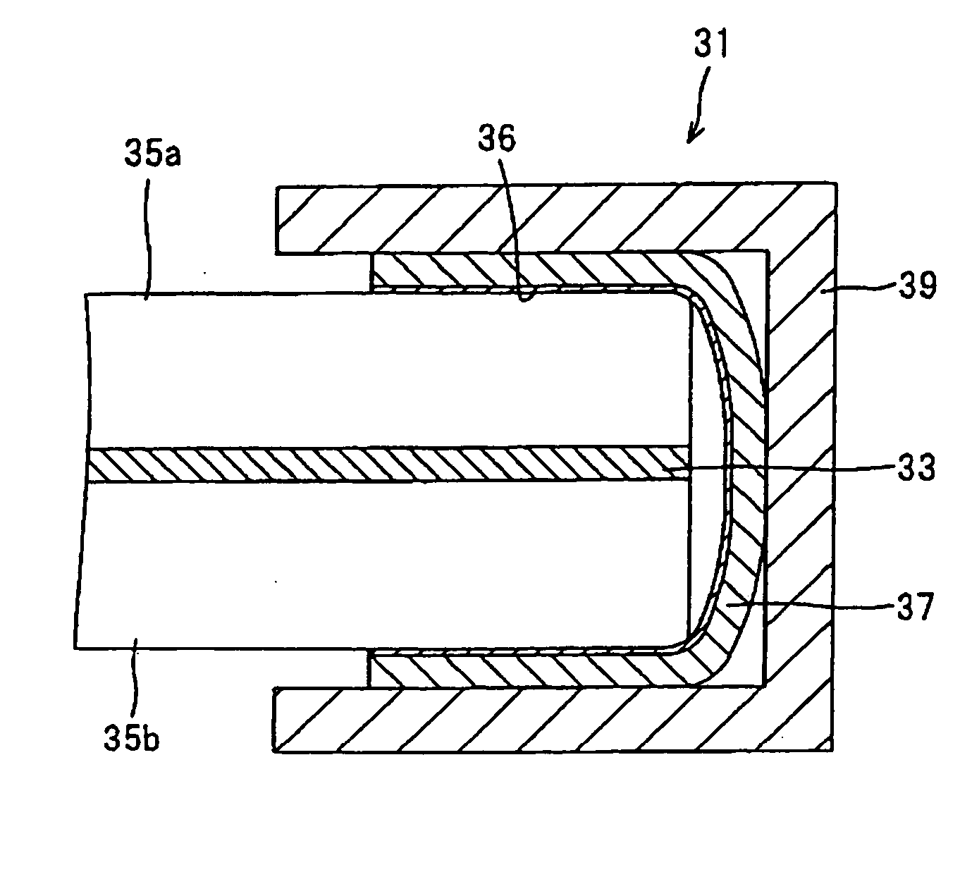
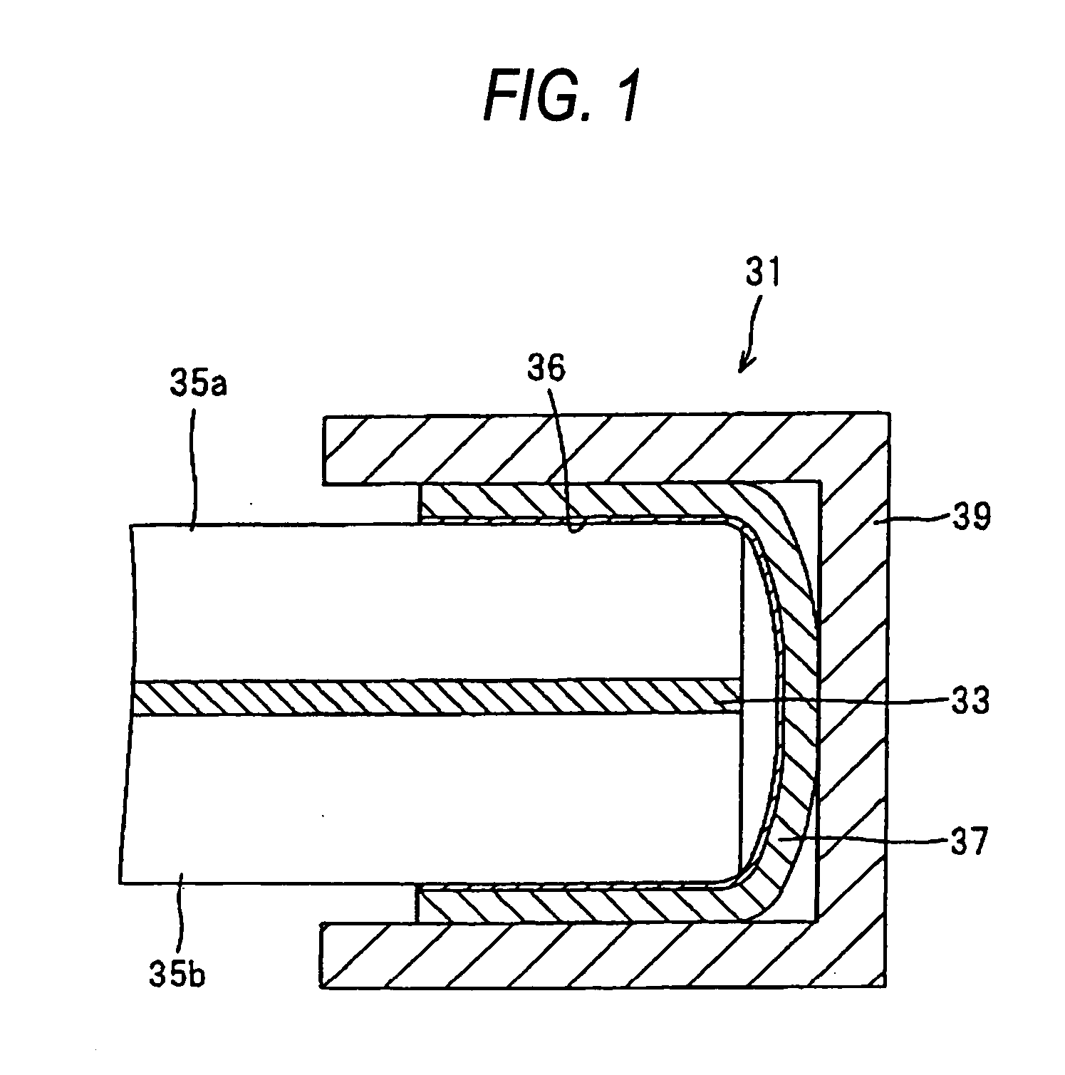
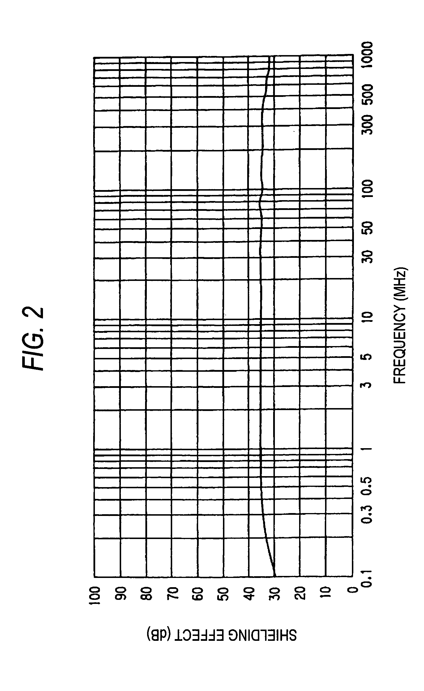
[0067]FIG. 1 is an enlarged cross section of a major portion showing an electromagnetic wave shielding window of the invention. FIG. 2 is a graph showing the shielding characteristic when a mesh member is used as a conductive shielding layer. FIG. 3 is a graph showing the shielding characteristic when a film member is used as the conductive shielding layer.

[0068] An electromagnetic wave shielding window 31 of this embodiment is composed of a sheet-like conductive shielding member conductive shielding layer 33 having the visible light transmitting property, a pair of window face members 35a and 35b sandwiching the conductive shielding member 33 from the main and back surfaces and having the electrical insulating property and the visible light transmitting property, a conductive adhesive tape 37 laminated to surround the rims of the pair of window face members 35a and 35b entirely with predetermined opposing widths to form a U-shaped cross section, and a conductive window frame member...

second embodiment

[0087] the electromagnetic wave shielding window of the invention will now be explained.

[0088]FIG. 6 is an enlarged cross section of a major portion showing the second embodiment of the electromagnetic wave shielding window of the invention. In the respective embodiments described below, the same members as the members shown in FIG. 1 are labeled with the same reference numerals, and the duplicate explanation will be omitted.

[0089] An electromagnetic wave shielding window 61 of this embodiment is composed of a single window face member 35 having the electrical insulating property and the visible light transmitting property, a sheet-like conductive shielding member 33 laminated to one surface of the window face member 35 and having the visible light transmitting property, a conductive adhesive tape 37 laminated to surround the rim of the window face member 35, to which the conductive shielding member 33 is laminated, entirely with a predetermined width to form a U-shaped cross secti...

third embodiment

[0092] the electromagnetic wave shielding window of the invention will now be explained.

[0093]FIG. 7 is an enlarged cross section of a major portion showing the third embodiment of the electromagnetic wave shielding window of the invention.

[0094] An electromagnetic wave shielding window 71 of this embodiment is arranged in such a manner that a protection sheet 73 having the electrical insulating property and deposited on the entire surface of the conductive shielding member 33 is used as the insulation layer 62 in the second embodiment. The other arrangements are the same as those of the aforementioned electromagnetic wave shielding window 61.

[0095] With the electromagnetic wave shielding window 71, the protection sheet 73 having the electrical insulating property is further deposited across the front surface of the conductive shielding member 33 laminated to one surface of the window face member 35, and the conductive shielding member 33 and the conductive adhesive tape 37 are pl...


PUM

PropertyMeasurementUnit
frequencyaaaaaaaaaa
widthsaaaaaaaaaa
thicknessaaaaaaaaaa

Abstract

The present invention provides an electromagnetic wave shielding method and window capable of bringing a conductive shielding layer into conduction to the outside without a connecting structure, and a manufacturing apparatus, a transport system, and a building construction each having the electromagnetic wave shielding window. In the invention, a conductive shielding layer having a visible light transmitting property is provided on a surface of window face members having an electrical insulating property and a visible light transmitting property, and the window face members provided with the conductive shielding layer are brought into close adhesion and thereby fixed to a conductive window frame member through an insulation layer provided to a rim portion, whereby electrostatic-capacitance coupling is induced between the conductive shielding layer and the window frame member. It leads to achieve the electromagnetic wave shielding effect without establishing a direct electrical connection for the conductive shielding layer.

Description

BACKGROUND OF THE INVENTION [0001] 1. Field of the Invention [0002] The present invention relates to an electromagnetic wave shielding method and an electromagnetic wave shielding window for allowing passing of visible light while reducing passing of an electromagnetic wave to a predetermined level or below, a manufacturing apparatus having the electromagnetic wave shielding window, a transport system having the electromagnetic wave shielding window, and a building construction having the electromagnetic wave shielding window. [0003] 2. Description of the Related Art [0004] Recently, emission of unwanted electromagnetic energy has been on the increase with increasing use of electric energy, and adverse effects of such emission to environments are being concerned. The environmental issues posed by an electromagnetic wave include: mutual interference of channels and ghosts of a broadcast wave in regard to wireless communications; the safety of a robot system in regard to a manufacturi...

Claims


Application Information

Patent Timeline
Patent Type & Authority Applications(United States)
IPC IPC(8): E06B5/18H05K9/00H05K13/04
CPCB64C1/1492Y10S428/914H05K9/00E06B5/18Y10T428/31678
Inventor HIKITA, OSAMUKAKIMOTO, TAKASHI
Owner PANASONIC CORP
Why Eureka
Try Eureka