Method and supply line structure for transmitting data between electrical automotive components

a technology for automotive components and supply lines, applied in the field of transmission methods of electrical components, can solve the problems of limited powerline communications, powerline communications may only be operated, information to be transmitted via the supply line structure may arrive at the receiving component significantly attenuated, etc., to achieve the effect of enhancing the fail-safe feature of the bus system and reducing cost and labor

Inactive Publication Date: 2005-02-24
ROBERT BOSCH GMBH
View PDF12 Cites 28 Cited by
  • Summary
  • Abstract
  • Description
  • Claims
  • Application Information

AI Technical Summary

Benefits of technology

[0009] The present invention may enhance the fail-safe feature of a bus system, such as, for example, for use in areas relevant to the safety of the motor vehicle, with reduced cost and labor.
[0012] Transmission of information via the supply line structure may also be referred to as powerline communications. Due to the additional transmission of information via the supply line structure in addition to via the data bus, an at least partially redundant channel may be available in an existing bus system. Even if the entire communication network of the vehicle cannot be configured to be redundant via the supply line structure, an emergency function or a limp-home function may be performed in any case via this channel. In this manner, failure of an electrical component due to a fault in the information transmission to other components, or even to total failure of the entire motor vehicle, may be prevented. Susceptibility to failure of the bus system according to the present invention may be substantially less than that of the data bus alone.
[0014] Using an exemplary embodiment and / or exemplary method of the present invention, the communication link between systems relevant to safety may be ensured and the fail-safe feature of the system may be enhanced. No additional lines may be required to be installed to implement the redundant transmission link, whereby the additional complexity and additional costs of the second transmission link may be minimized. The supply line structure may be already relevant to safety, because communication may occur over supply lines which may not be permitted to fail because of the power supply in systems relevant to safety.
[0019] If information transmission over the data bus is functioning properly, other information may be transmitted over the supply line structure. This communication on the supply line structure, which may be independent of the information transmission over the data bus, may be interrupted if needed in order to enable transmission of information over the supply line structure in the event of faulty information transmission over the data bus. As an alternative, communication may also continue over the supply line structure, a smaller bandwidth being then available for the information transmission via the supply line structure as a substitute for transmission via the data bus. This bandwidth may, however, be adequate for taking over a vital portion of the information transmission from the data bus, thus the possibility of an emergency operation may be ensured.

Problems solved by technology

Presently powerline communications may only be operated with limitations in supply line structures provided in motor vehicles, because the information to be transmitted via the supply line structure may arrive at the receiving component significantly attenuated due to interference and reflection or may not even be distinguishable from interference or noise signals.
The powerline communications described therein may be limited to the use for electrical components of a backing-up aid in a motor vehicle.
The redundant configuration of the bus systems using a plurality of data buses, however, may result in increased material costs for the additional data bus and in increased labor and cost for routing the additional data bus in the motor vehicle.

Method used


Image

  • Method and supply line structure for transmitting data between electrical automotive components
  • Method and supply line structure for transmitting data between electrical automotive components
  • Method and supply line structure for transmitting data between electrical automotive components

Examples


Embodiment Construction

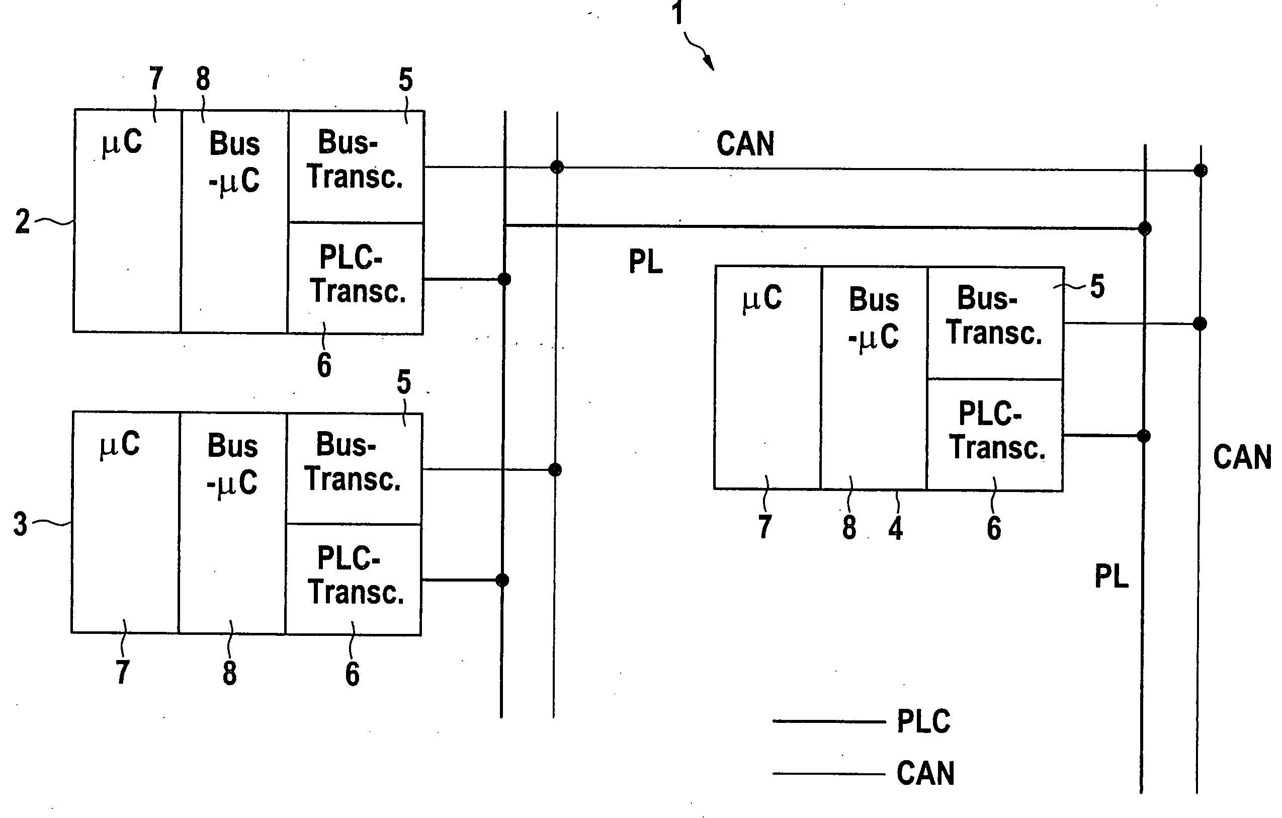
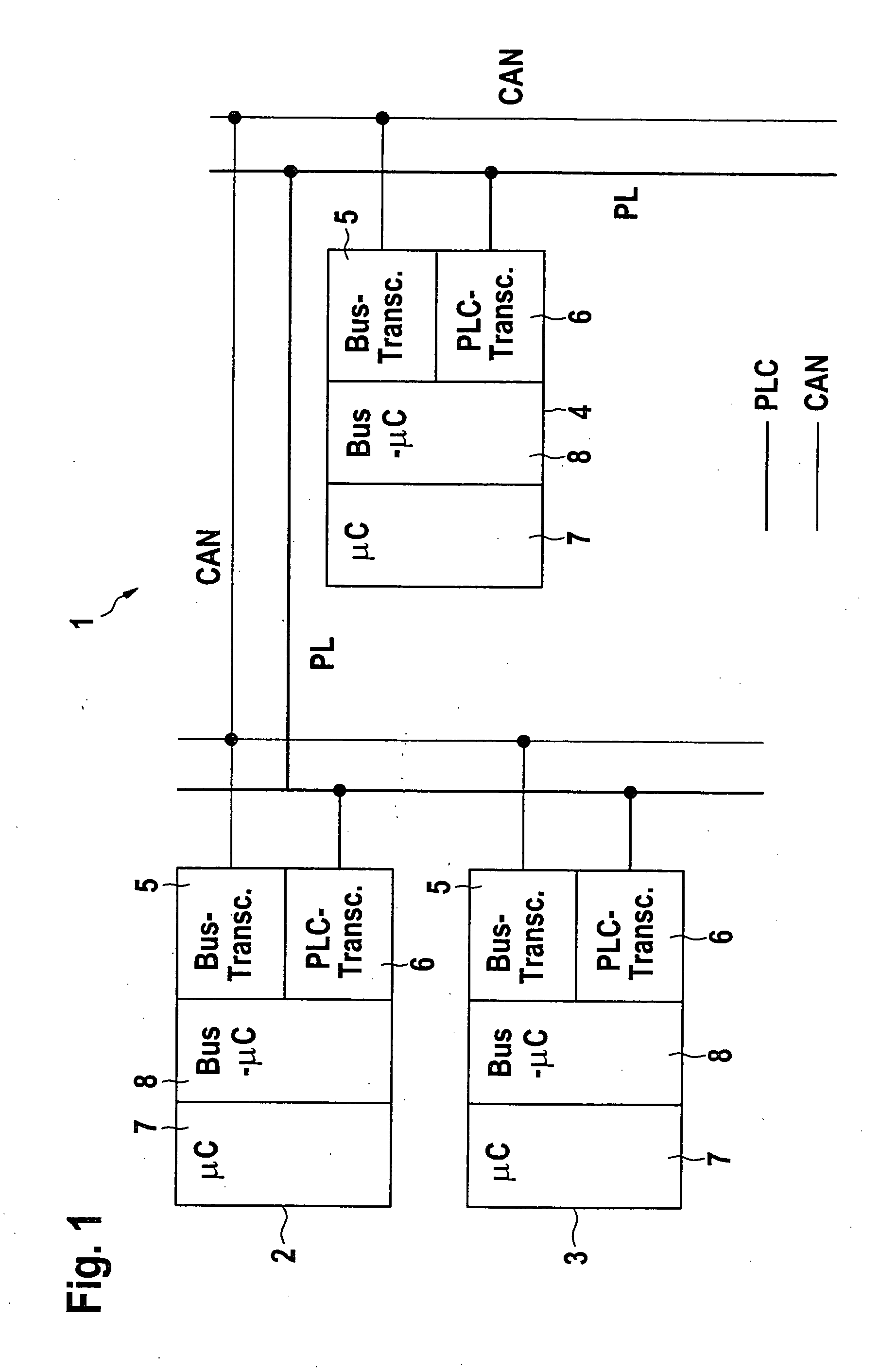
[0029]FIG. 1 shows a bus system according to an exemplary embodiment of the present invention identified in its entirety with the symbol 1. Bus system 1 is used for transmitting information between electrical components 2, 3, 4 in a motor vehicle. Electrical components 2, 3, 4 may be control units, for example, for different motor vehicle functions, including, for example, control units in areas relevant to the safety of the motor vehicle, such as, for example, an internal combustion engine, a power train, a brake system, or any other X-by-wire application. However, hydraulic or pneumatic or other types of electrically triggerable components may also be defined as electrical components 2, 3, 4 in the sense of the present invention.

[0030] Bus system 1 includes a standardized data bus, which is intended for the transmission of information. The data bus in the present exemplary embodiment is configured as a controller area network (CAN) bus and depicted in FIG. 1 by a thin line. Elect...


PUM


Abstract

A method and a supply line structure for transmitting information between electrical components in a motor vehicle is described. The information is transmitted over a data bus. At least some of the components are powered via a supply line structure. To make the transmission of information between the components fail-safe, the information is also transmitted over the supply line structure in addition to over the data bus at least after a failure of the data bus.

Description

FIELD OF THE INVENTION [0001] The present invention relates to a method for transmitting information between electrical components in a motor vehicle. The information may be transmitted over a data bus. At least some of the components may be powered via a supply line structure. [0002] Furthermore, the present invention relates to a bus system for transmitting information between electrical components in a motor vehicle. The bus system may include a data bus. At least some of the components may be connected to the supply line structure provided in the motor vehicle for powering the components. [0003] The present invention furthermore may include an electrical component of a motor vehicle which has an arrangement for transmitting information to other electrical components via a data bus and for receiving information from other electrical components via a data bus. The component and at least some of the other components may be connected to a supply line structure for power supply. BACK...

Claims


Application Information

Patent Timeline
Patent Type & Authority Applications(United States)
IPC IPC(8): B60R16/02B60R16/03H04L12/40H04B3/28H04B3/54H04B3/56H04L12/413H04L69/14H04L69/40
CPCB60R16/0315B60T2270/82H04B3/28H04B3/54H04B2203/5445H04B2203/547Y10S307/01H04L12/10H04L12/40189H04L2012/40215H04L2012/40273H04L69/40H04L1/22
Inventor ENDERS, THORSTENHUGEL, ROBERT
Owner ROBERT BOSCH GMBH
Why Eureka
Try Eureka