Full bridge power converters with zero-voltage switching

a converter and bridge technology, applied in the direction of electric variable regulation, process and machine control, instruments, etc., can solve the problems of conduction loss and switching loss, conduction loss, switching loss is associated,

Inactive Publication Date: 2005-02-24
DELTA ELECTRONICS INC
View PDF2 Cites 58 Cited by
  • Summary
  • Abstract
  • Description
  • Claims
  • Application Information

AI Technical Summary

Benefits of technology

Finally, it should be noted that the circuits of this invention can be implemented with any type of secondary-side rectifier, for example, a full-wave rectifier with a center-tap secondary winding, full-wave rectifier with a current doubler, or a full-bridge full-wave rectifier. In addition, in all embodiments of the present invention, the primary inductor used for ZVS energy storage can be eliminated by utilizing the leakage inductance of the auxiliary transformer to store the required energy.

Problems solved by technology

Switching power converters usually suffer from two types of losses: conduction losses and switching losses.
Conduction losses are associated with energy dissipation in the form of heat due to resistive converter elements.
Switching losses are associated with the switching elements of the power converter.
Since the leakage inductance LLK is small, the energy stored in LLK is also small so that ZVS of Q1 and Q2 is hard to achieve even at relatively high load currents, for example, when the delivered power to the load is at the rated power of the converter.
However, a large external inductor also stores an excessive amount of energy at full load, i.e., when the delivered power is equal to the rated power, which produces a relatively large circulating energy that increases semiconductor components stress, as well as conversion efficiency.
This extended commutation time results in a loss of duty cycle on the secondary of the transformer, which further decreases the conversion efficiency.
With a smaller transformer turn-ratio, however, the reflected output current into the primary is increased, which increases the primary-side conduction losses, thereby creating undesired heat.
As a result, rectifiers with a higher voltage rating that typically have higher conduction losses may be required.
Yet another limitation of the circuit in FIG. 1 is a severe parasitic ringing at the secondary of the transformer during the turn-off of the rectifier.
While this circuit offers a practical and efficient solution to the secondary-side ringing problem, it does not offer any improvement in the secondary-side duty-cycle loss.
However, with the ever increasing need to increase power density or otherwise reduce the size of power converters, there is a requirement to decrease the size of the ZVS storage inductor.

Method used


Image

  • Full bridge power converters with zero-voltage switching
  • Full bridge power converters with zero-voltage switching
  • Full bridge power converters with zero-voltage switching

Examples


Embodiment Construction

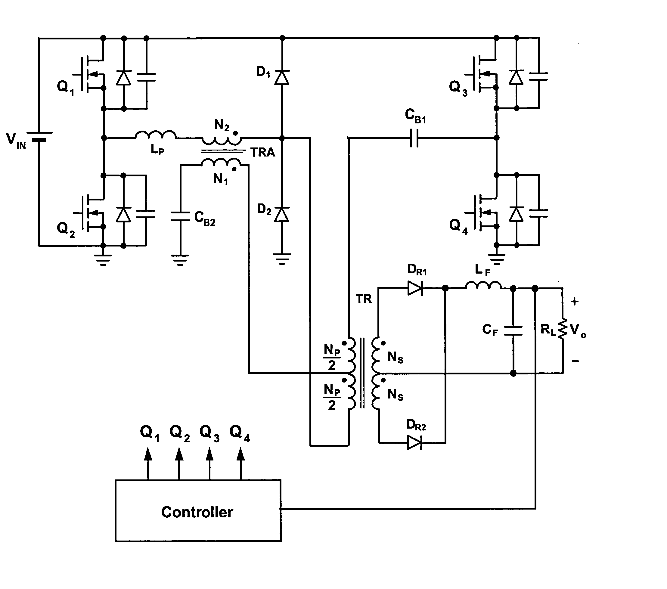
FIG. 4 shows an exemplary embodiment for a converter in accordance with the present invention. The converter in FIG. 4 is a full bridge converter having an input port for receiving input power source VIN and an output port for supplying output power to load RL. The converter employs power transformer TR, auxiliary transformer TRA, and a bridge comprising leading-leg primary switches Q1 and Q2 and lagging-leg primary switches Q3 and Q4, which are controllable switching devices. A controller regulates the load current by periodically switching controllable switching devices Q1, Q2, Q3 and Q4 into on and off states. Also included in the exemplary converter of the present invention is primary inductance LP, capacitor CB2, primary diodes D1 and D2, and blocking capacitor CB1. On the secondary side, the converter in FIG. 4 includes rectifiers DR1 and DR2 and a low pass filter comprising Lf and Cf. As described further in detail below, the present invention provides an isolated phase shift...


PUM


Abstract

A soft-switched, full-bridge pulse-width-modulated (FB PWM) converter and its variations provide zero-voltage-switching (ZVS) conditions for the turn-on of the bridge switches over a wide range of input voltage and output load. The FB PWM converters of this invention achieve ZVS with a substantially reduced duty cycle loss and circulating current, which optimizes the conversion efficiency. The ZVS of the primary switches is achieved by employing an auxiliary circuit comprising an inductor and transformer to store energy for ZVS turn-on of the bridge switches.

Description

BACKGROUND OF THE INVENTION 1. Field of the Invention This invention generally relates to the field of power converters, and more particularly, to full bridge converters that operate with zero-voltage switching (ZVS). 2. Description of the Prior Art Full-bridge switching power converters are a common DC / DC conversion topology used for supplying high power to a wide variety of electronic components, including telecommunication equipments, computers, servers, etc. A DC / DC switching converter contains an input port typically coupled to a DC power source, such as a battery, to provide DC power to a load connected to an output port. In general, full-bridge converters utilize two bridge legs with four switching elements in the primary side of a transformer that isolates the input port from the output port. Usually, a pulse width modulator is used to regulate the output voltage under various load conditions. Important considerations in the design of converters include power density an...

Claims


Application Information

Patent Timeline
Patent Type & Authority Applications(United States)
IPC IPC(8): H02M3/335H02M7/5387
CPCH02M7/5387H02M3/33569H02M3/33573H02M3/01
Inventor JANG, YUNGTAEKJOVANOVIC, MILAN M.
Owner DELTA ELECTRONICS INC
Why Eureka
Try Eureka