Optical fiber coupling having liquid crystal adaptive coupler

Inactive Publication Date: 2005-02-24
TELEDYNE SCI & IMAGING
View PDF4 Cites 2 Cited by
  • Summary
  • Abstract
  • Description
  • Claims
  • Application Information

AI Technical Summary

Benefits of technology

[0011] It is another object of the invention to provide an optical beam steering device that improves the optical coupling efficiency between a source of the beam and a receiving optical waveguide.
[0012] It is a further object of the present invention to provide an optical beam steering device that improves the optical coupling efficiency between an input optical waveguide and an output optical waveguide.
[0013] It is a further object of the present invention to provide an optical beam steering device that improves the optical coupling efficiency between an input optical waveguide and an output optical waveguide by correcting for imperfections in one or more lenses disposed in the optical path and/or for misalignments of the input and/or output optical waveguides.
[0014] It is a further object of the present invention to provide an optical beam steering device that improves the optical coupling efficiency between an input optical waveguide and an ou

Problems solved by technology

A drawback of striped electrode liquid crystal cell beam steering devices is that they tend to introduce crosstalk due to diffraction.
Another disadvantage of striped electrode beam steerers systems is that they limit the available beam steering angles to discrete angular increments.
This limitation results from the digital nature of these devices as well as from the striped electrode interconnection and drive schemes.
Although large subarrays can accommodate many possible integer factors (and thus many steerable angles), the steerable angle is still limited to discrete increments; it is not continuously variable.
None of those devices deal

Method used


Image

  • Optical fiber coupling having liquid crystal adaptive coupler
  • Optical fiber coupling having liquid crystal adaptive coupler
  • Optical fiber coupling having liquid crystal adaptive coupler

Examples


Embodiment Construction

[0036] It will be evident to those skilled in the art that the present invention has broad utility, being applicable, by way of example and not limitation, to cross bar switches; filter arrays; attenuator arrays; antenna arrays; laser systems utilizing, for example, laser diode sources for communications or other purposes; and so forth, employing optical channels or waveguides which may take the form of optical fibers.

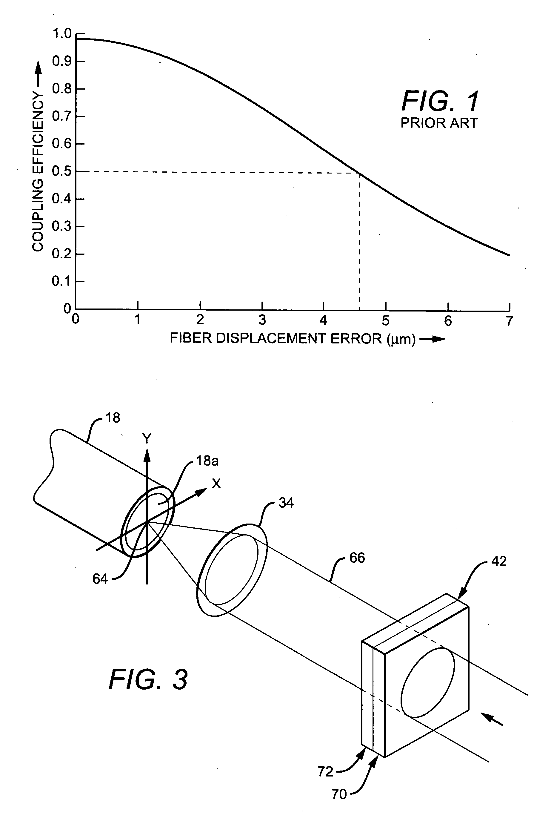
[0037] With reference to FIG. 2, there is shown a specific example of how the present invention may be applied. The example of FIG. 2 comprises a form of an N×N liquid crystal optical cross connect switch 10 for use, for example, in a data communications or telecommunications system.

[0038] In the specific, exemplary N×N optical switch shown in FIG. 2, N=4 so that the switch 10 can couple any selected one of four longitudinally oriented input fibers 14 with any selected one of four longitudinally oriented output fibers 18.

[0039] A support 24 secures the light-emittin...


PUM


Abstract

An apparatus for optically coupling a light source with a light-receiving end face of an optical waveguide comprises a lens for focusing a light beam emitted from the light source at a focal point on the light-receiving end face of the optical waveguide. An adaptive coupler, positioned in the optical path, is responsive to a beam steering control signal for steering and aligning the focal point relative to the light-receiving end face of the optical waveguide. In one form, the adaptive coupler comprises a pair of transparent substrates having confronting, parallel inner faces, the inner face of one of the pair of substrates carrying a beam intercepting, optically transparent, constant potential electrode and the inner face of the other of the pair of substrates carrying an electrically resistive, beam intercepting, optically transparent film. A pair of spaced apart electrodes in electrical contact with the film apply a linear voltage gradient along the film. An electro-optical phase shifting medium is disposed between the confronting inner faces of the substrates. The application of selected voltages to the electrodes creates a linear voltage gradient along the aforementioned film on the inner face of the one substrate resulting in a linearly varying electric field between that film and the constant potential electrode creating a corresponding linear variation in the refractive index of the liquid crystal medium and a linear wavefront tilt in the intercepting optical beam.

Description

BACKGROUND OF THE INVENTION [0001] 1. Field of the Invention [0002] The present invention relates generally to optical beam steering and particularly to an optical system utilizing the electro-optical properties of liquid crystals to steer a light beam relative to a light-receiving end of an optical waveguide such as an optical fiber. [0003] 2. Description of the Related Art [0004] N×N optical cross connect switches used, for example, in telecommunications systems, optically couple any one of N input optical fibers to any one of N output optical fibers. Such switches comprise examples of systems that make use of various techniques for deflecting or steering a light beam emitted from a light source, in this case the light-emitting end of a selected one of the N input fibers, to the light-receiving end of an optical waveguide, here in the form of a selected one (and in some cases, more than one) of the N output fibers. [0005] One conventional optical beam steering technique applies di...

Claims


Application Information

Patent Timeline
IPC IPC(8): G02B6/32G02B6/35G02F1/139G02F1/29
CPCG02B6/32G02B6/351G02F1/292G02F1/1392G02B6/3556
Inventor GU, DONG-FENGTABER, DONALD B.WINKER, BRUCE K.
Owner TELEDYNE SCI & IMAGING
Why Eureka
Try Eureka