Contrast based resolution enhancement for photolithographic processing

a technology of resolution enhancement and photolithography, applied in the field of resolution enhancement technologies (ret) in photolithography, can solve the problems of reducing reducing the efficiency increasing the density of the components, so as to improve the overall contrast of the layout design, improve the manufacturability of layout design, and increase the contrast of edge fragments.

Inactive Publication Date: 2005-02-24
SIEMENS PROD LIFECYCLE MANAGEMENT SOFTWARE INC
View PDF26 Cites 50 Cited by
  • Summary
  • Abstract
  • Description
  • Claims
  • Application Information

AI Technical Summary

Benefits of technology

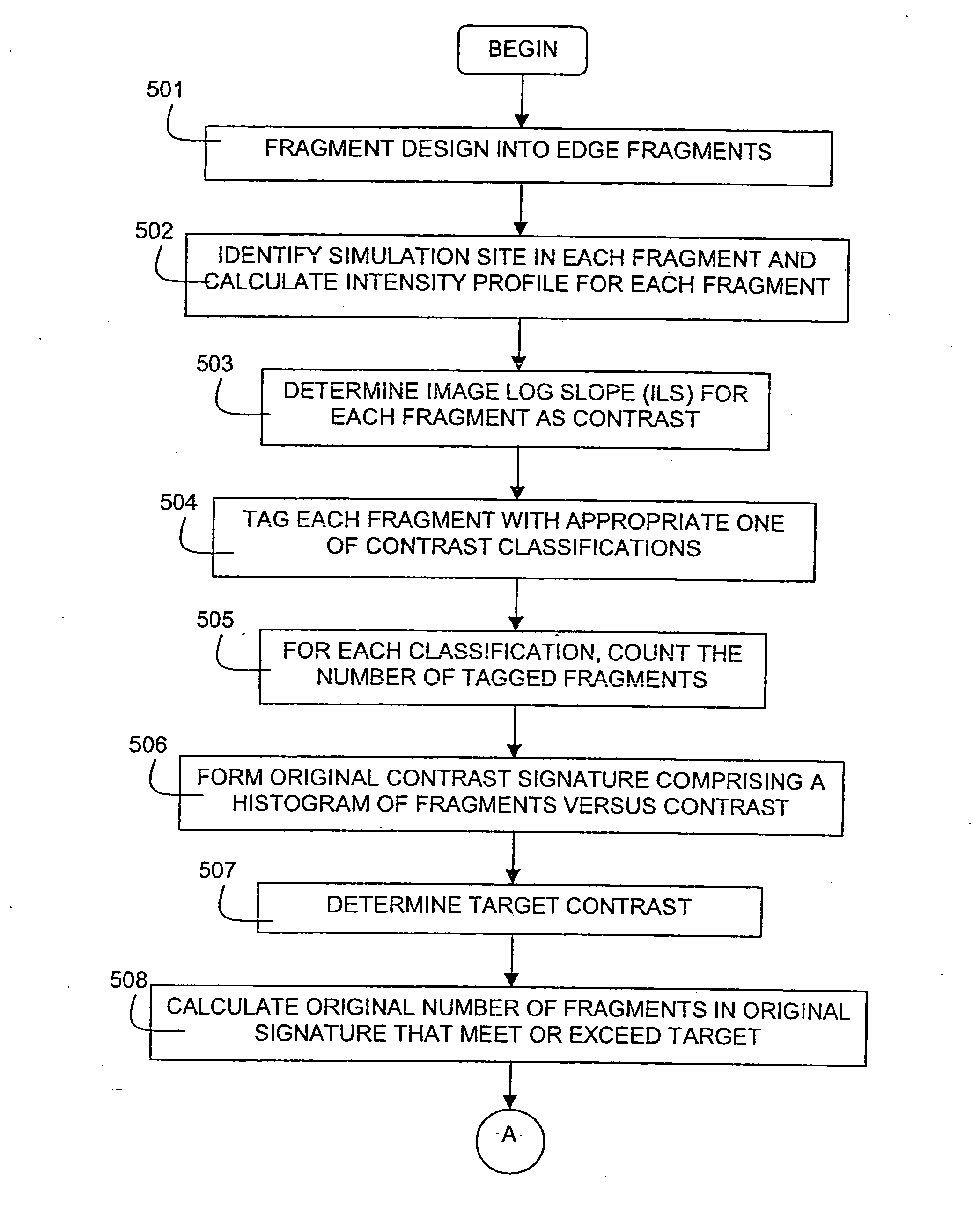
To improve the manufacturability of layout designs for photolithographic processing, the present invention applies one or more resolution enhancement techniques (RETs) to increase the contrast of edge fragments that comprise at least a portion of the layout design.
In one embodiment, edge fragments are categorized into a range of contrast values. An RET is applied to the edge fragments within a range of contrast values that maximize the number of edge fragments having contrast values above a threshold. An RET can be applied to edge fragments having another range of contrast values to improve the overall contrast of the layout design.

Problems solved by technology

Market pressures, however, continually drive for smaller components, higher density, and greater functionality.
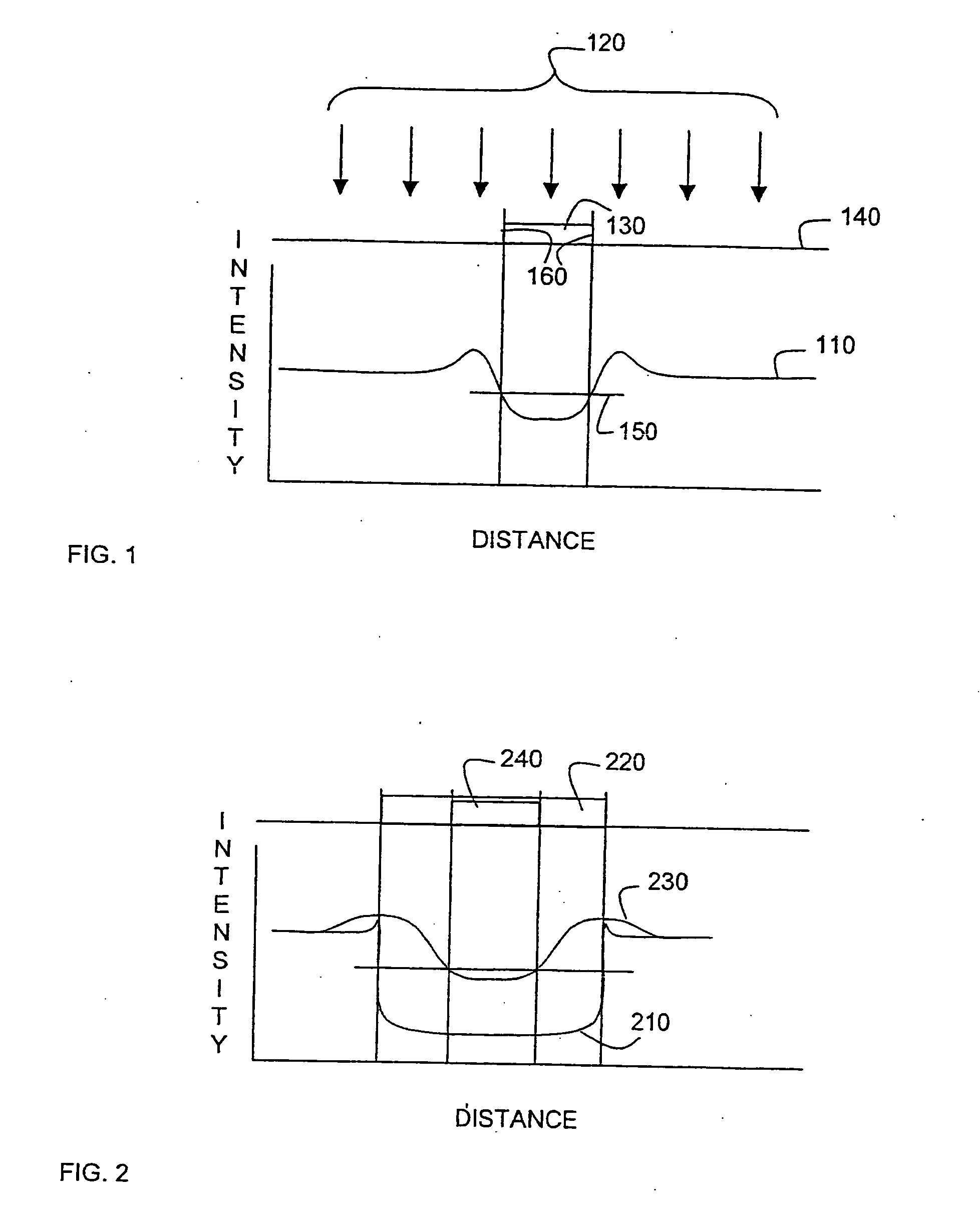
This change of the intensity pattern as feature sizes near or drop below the wavelength of the light source creates a number of design challenges.
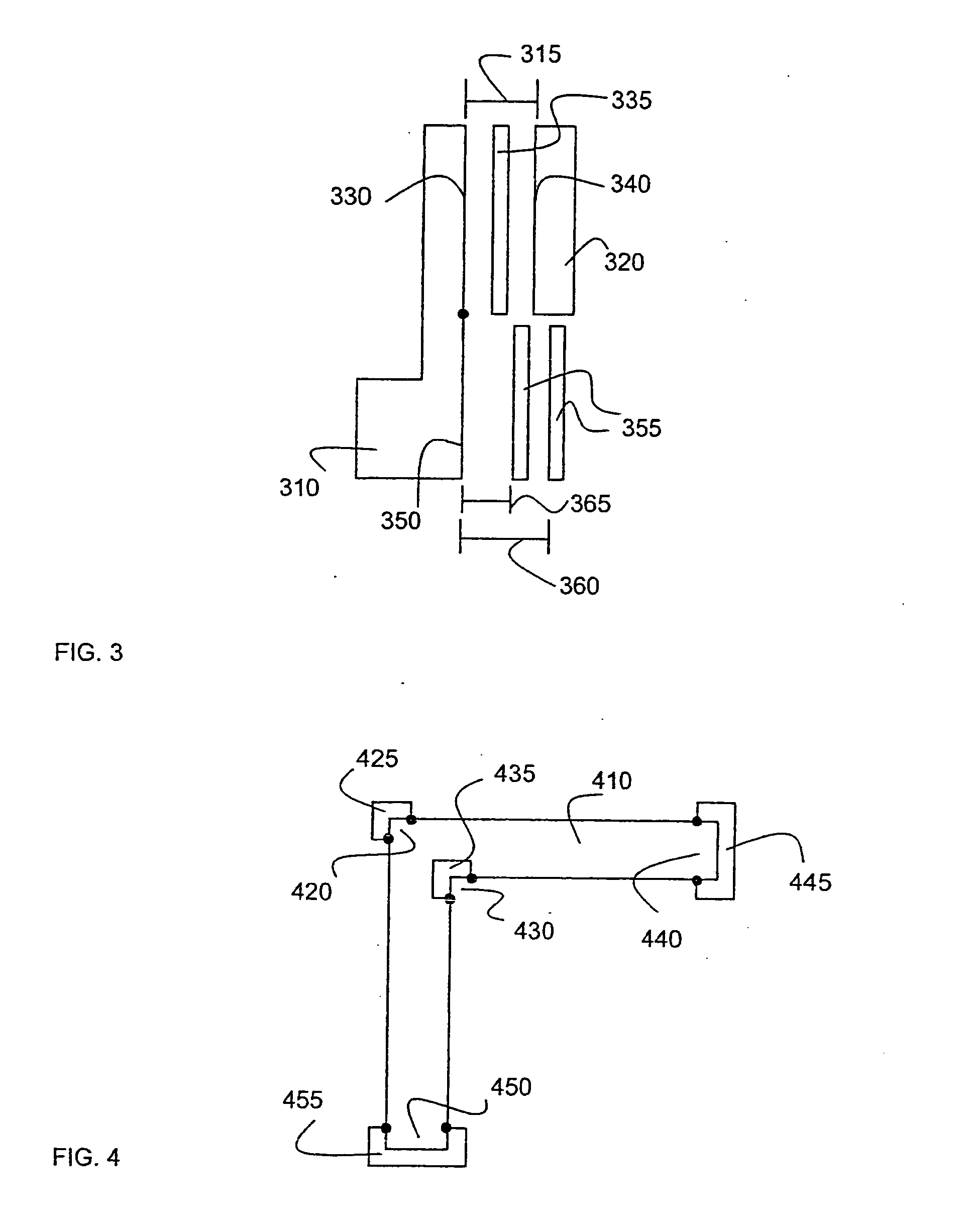
Edge placement becomes increasingly less precise, often leading to the ends of lines being cut off and sharp corners being rounded.
Neighboring features become increasingly interdependent as their intensity patterns overlap, often causing features to “bleed” into each other or not resolve at all.
Edges that run diagonally through a design are often difficult to classify to either a horizontal or a vertical dipole mask.
And, features may have complex shapes that are interwoven with multiple neighbors, making it very difficult to classify edges of neighboring features to different phases in PSM.

Method used


Image

  • Contrast based resolution enhancement for photolithographic processing
  • Contrast based resolution enhancement for photolithographic processing
  • Contrast based resolution enhancement for photolithographic processing

Examples


Embodiment Construction

In the following detailed description, numerous specific details are set forth in order to provide a thorough understanding of the present invention. However, those skilled in the art will understand that the present invention may be practiced without these specific details, that the present invention is not limited to the depicted embodiments, and that the present invention may be practiced in a variety of alternate embodiments. In other instances, well known methods, procedures, components, and circuits have not been described in detail.

Parts of the description will be presented using terminology commonly employed by those skilled in the art to convey the substance of their work to others skilled in the art. Also, parts of the description will be presented in terms of operations performed through the execution of programming instructions. As well understood by those skilled in the art, these operations often take the form of electrical, magnetic, or optical signals capable of b...


PUM

PropertyMeasurementUnit
threshold contrastaaaaaaaaaa
sizeaaaaaaaaaa
distanceaaaaaaaaaa

Abstract

A contrast-based resolution enhancing technology (RET) determines a distribution of contrast values for edge fragments in a design layout or portion thereof. Resolution enhancement is applied to the edge fragments in a way that increases the number of edge fragments having a contrast value that exceeds a predetermined threshold.

Description

FIELD OF THE INVENTION The present invention pertains to the field of Resolution Enhancing Technologies (RET) in photolithography. More particularly, this invention relates to using contrast measurements to improve the resolution of features to be created via a photolithographic process. BACKGROUND OF THE INVENTION In photolithography, a pattern is transferred onto a surface by shining a light through a mask (or reticle) containing the pattern onto a photosensitive material covering the surface. The light exposes the photo-sensitive material in the pattern of the mask. A chemical process etches away either the exposed material or the unexposed material, depending on the particular process that is being used. Another chemical process etches into the surface wherever the photosensitive material was removed. The result is the pattern itself, either imprinted into the surface where the surface has been etched away, or protruding slightly from the surface as a result of the surrounding...

Claims


Application Information

Patent Timeline
Patent Type & Authority Applications(United States)
IPC IPC(8): G03C5/00G03F1/14G06F17/50G06G7/62G06K9/00
CPCG03F1/144G06F2217/12G06F17/5068G03F1/36G06F30/39G06F2119/18Y02P90/02
Inventor ROBLES, JUAN ANDRES TORRESGRANIK, YURI
Owner SIEMENS PROD LIFECYCLE MANAGEMENT SOFTWARE INC
Why Eureka
Try Eureka