
Cleaning apparatus and cleaning method

a technology of cleaning apparatus and cleaning method, which is applied in the direction of cleaning equipment, cleaning equipment, chemical equipment and processes, etc., can solve the problems of time-consuming apparatus adjustment operation, failure to achieve a complete recovery of dust, and leakage of air blowing to the outside, so as to reduce maintenance costs, plant investment, and reduce running costs

Inactive Publication Date: 2005-03-03
SONY CORP
View PDF10 Cites 23 Cited by
  • Summary
  • Abstract
  • Description
  • Claims
  • Application Information

AI Technical Summary

Benefits of technology

[0018] The present invention has been made under the above-described circumstances to provide a cleaning apparatus and a cleaning method at low cost, with which it is able to remove not only dust but also liquid, while preventing the readherence of dust to a cleaning object, so that cleaning is performed without requiring a dust collector by means of vacuum or the like.
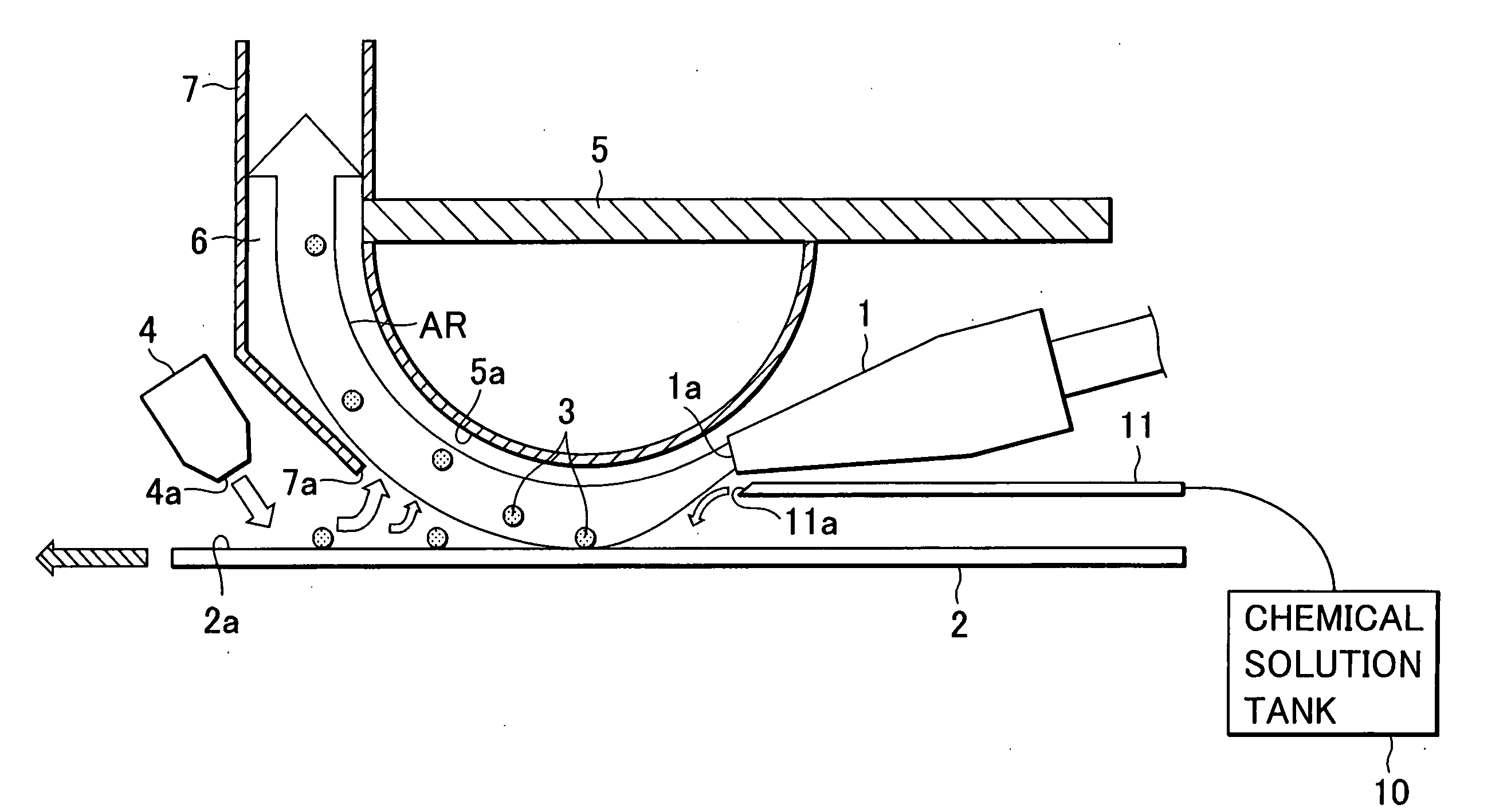
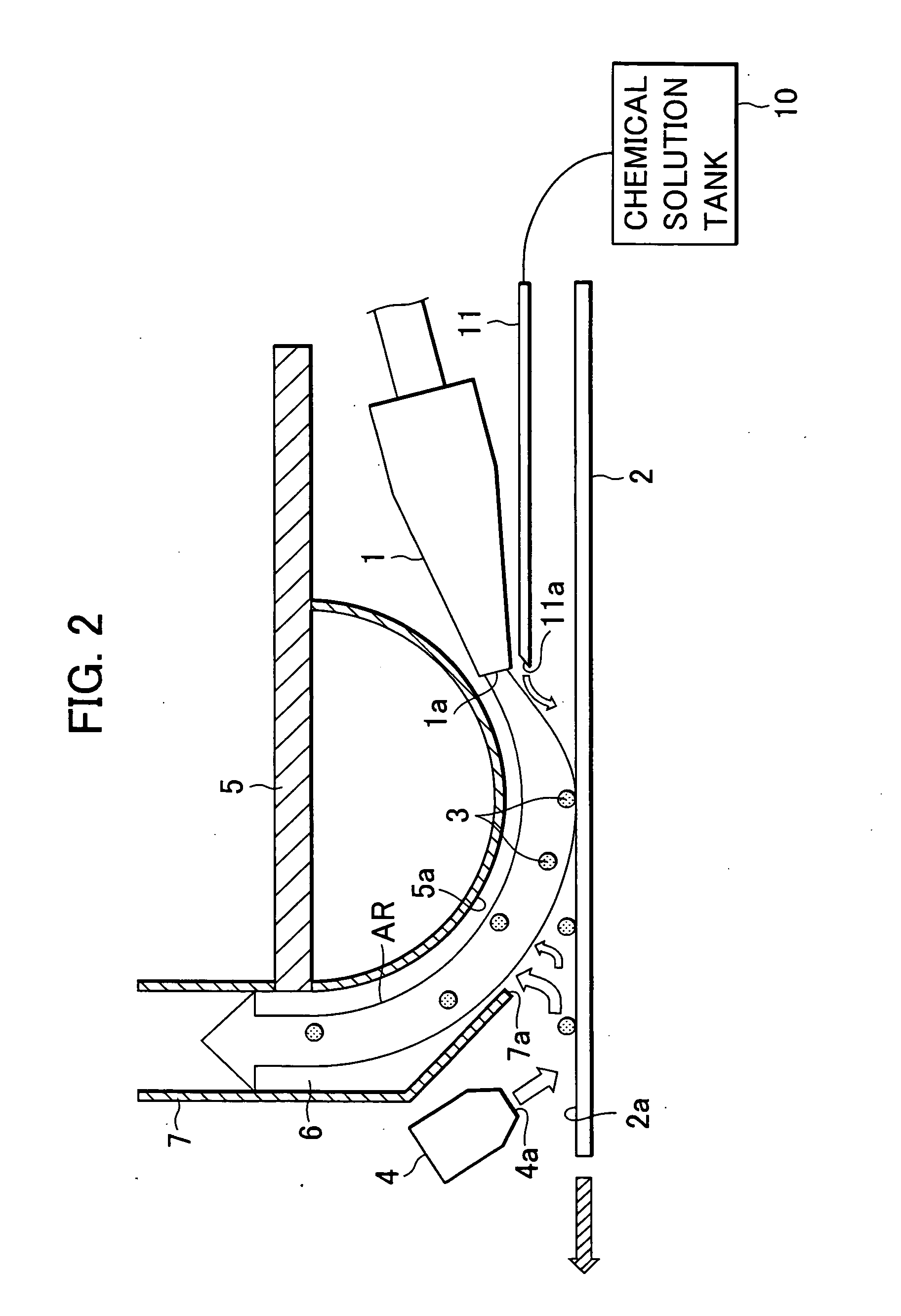
[0020] As described above, in accordance with the cleaning apparatus of the present invention, the recovery means for recovering the air containing the dust removed by spraying the high pressure air is disposed in front of the outlet port of the air nozzle, and it is constructed such that the air containing the dust removed is exhausted into the exhaust introducing passage along the wall surface of the air guide of the recovery means. It is therefore able to remove the dust from the cleaning object in a simple structure, without using a dust collector by means of vacuum, which is expensive and requires a large installation area.
[0023] In accordance with the cleaning apparatus of the present invention, there is used the recovery means of simple structure to make the deposit removed to be exhausted into the exhaust introducing passage along the wall surface by utilizing Coanda effect and recovered. It is therefore able to attain plant investment reduction, running cost reduction, and maintenance cost reduction, and it is also able to considerably reduce the apparatus installation space.
[0024] In accordance with the cleaning method of the present invention, it is able to remove the deposit of the cleaning object by high pressure air, and it is also able to, by Coanda effect, exhaust all of the air containing the removed deposit into the exhaust introducing passage and recover them without scattering it to the surroundings, thereby enabling to prevent readherence to the cleaning object. As a result, it is able to considerably reduce defective products caused by dust, thus enabling to improve productivity.

Problems solved by technology

It is thus considered that the removed dust may be scattered to work environment when the dust collector is stopped or depending on maintenance situations, failing to accomplish a complete recovery of the dust.
Therefore, the apparatus adjusting operation is time-consuming.
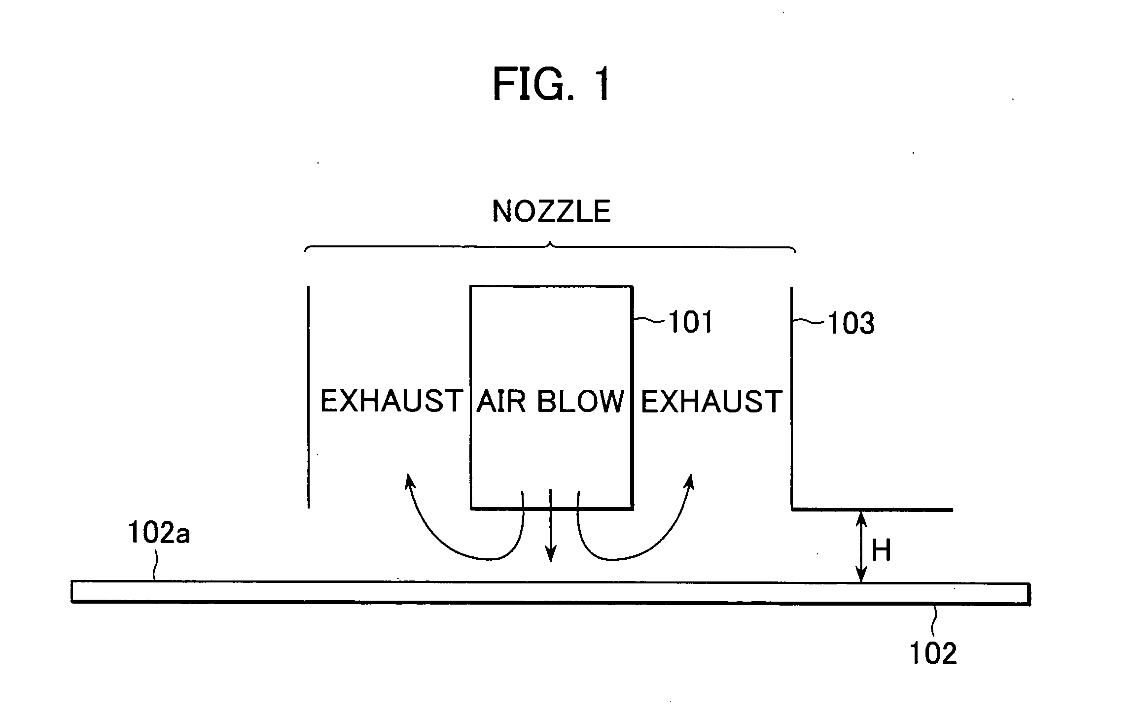
If the distance H is 5 mm or more, the suction force of the dust collector may be varied, and air blow leaks to the outside, failing to function as a cleaner.
Additionally, with these cleaning apparatuses, it is difficult to clean a cleaning object having on its surface swells or irregularities of 1 mm to 2 mm or more.
In addition, with these cleaning apparatuses, liquid adhered to a cleaning object cannot be removed because of the use of a large dust collector by means of vacuum, and they require a large apparatus installation area and a high level of plant investment, running cost such as electric and maintenance.
Furthermore, since the dust collector is used, it is difficult to use this cleaning apparatus under operational environment in the presence of explosive gas.
However, the dust adhered to a sticky matter readherence to the cleaning object, or it is impossible to remove liquid with this method.

Method used


Image

  • Cleaning apparatus and cleaning method
  • Cleaning apparatus and cleaning method
  • Cleaning apparatus and cleaning method

Examples


Embodiment Construction

[0032] Specific embodiments to which the present invention is applied will be described in detail by referring to the drawings.

[0033] [Configuration of Cleaning Apparatus]

[0034] A cleaning apparatus of this embodiment includes, as shown in FIG. 2, air supply means for spraying high pressure air from an air nozzle 1 obliquely onto a cleaning surface 2a of a cleaning object 2 to be cleaned; recovery means, disposed in front of an outlet port of the air nozzle 1, for recovering air AR containing deposit 3 removed from the cleaning object 2; ultrasound generating means for applying ultrasound waves to high pressure air sprayed onto the cleaning object 2; static electricity eliminating means having a static electricity eliminating nozzle 4 for eliminating static electricity charged on the cleaning surface 2a; and chemical solution supplymeans for sprayingachemical solution, such asasurface protection coating solution and a static electricity charge preventing solution, onto the cleaning...


PUM

PropertyMeasurementUnit
distanceaaaaaaaaaa
distanceaaaaaaaaaa
velocityaaaaaaaaaa

Abstract

A cleaning apparatus includes air supply means for spraying high pressure air obliquely onto a cleaning surface from an air nozzle disposed in vicinity of said cleaning surface of a cleaning object to be cleaned; and recovery means, disposed in front of an outlet port of said air nozzle, for recovering at least air containing foreign matter removed from said cleaning object by making said air exhaust into an exhaust introducing passage along a wall surface of an air guide. The recovery means is constituted by an air guide section disposed in front of the outlet port of the air nozzle, and an air cover section, which forms an exhaust introducing passage for recovering the air that flows along an air guide wall surface of the air guide section.

Description

CROSS REFERENCE TO RELATED APPLICATIONS [0001] The present document is based on Japanese Priority Document JP2003-275868, filed in the Japanese Patent Office on Jul. 17, 2003, the entire contents of which being incorporated herein by reference. BACKGROUND OF THE INVENTION [0002] 1. FIELD OF THE INVENTION [0003] The present invention relates to a cleaning apparatus and a cleaning method, which remove and recover foreign matter or dust, liquid and the like from a cleaning object to be cleaned by spraying, for example, high pressure air onto the cleaning object. Particularly, the present invention relates to a dust removing technique utilizing Coanda effect to make the recovery of the air containing the removed dust and the like into an exhaust introducing passage along a wall surface. [0004] 2. DESCRIPTION OF THE RELATED ART [0005] Conventionally, a number of techniques have been proposed as the technique of removing dust from a cleaning object. For example, in a patent document 1, th...

Claims


Application Information

Patent Timeline
Patent Type & Authority Applications(United States)
IPC IPC(8): B08B5/00B08B3/02B08B3/12B08B5/02B08B6/00B08B7/02B08B7/04B08B15/04H01L21/00H01L21/304
CPCB08B3/02B08B5/02H01L21/67051B08B15/04B08B7/028
Inventor WAKAO, MITSUNOBUTERAI, MASAKIOHSHIMA, YUKITOYO
Owner SONY CORP
Learn More