
Plasma processing apparatus

a technology of processing apparatus and plasma, which is applied in the direction of lighting and heating apparatus, refrigeration machines, coatings, etc., can solve the problems of large space occupation, poor temperature response, and inefficient heat use of temperature units

Inactive Publication Date: 2005-03-03
HITACHI HIGH-TECH CORP
View PDF11 Cites 79 Cited by
  • Summary
  • Abstract
  • Description
  • Claims
  • Application Information

AI Technical Summary

Benefits of technology

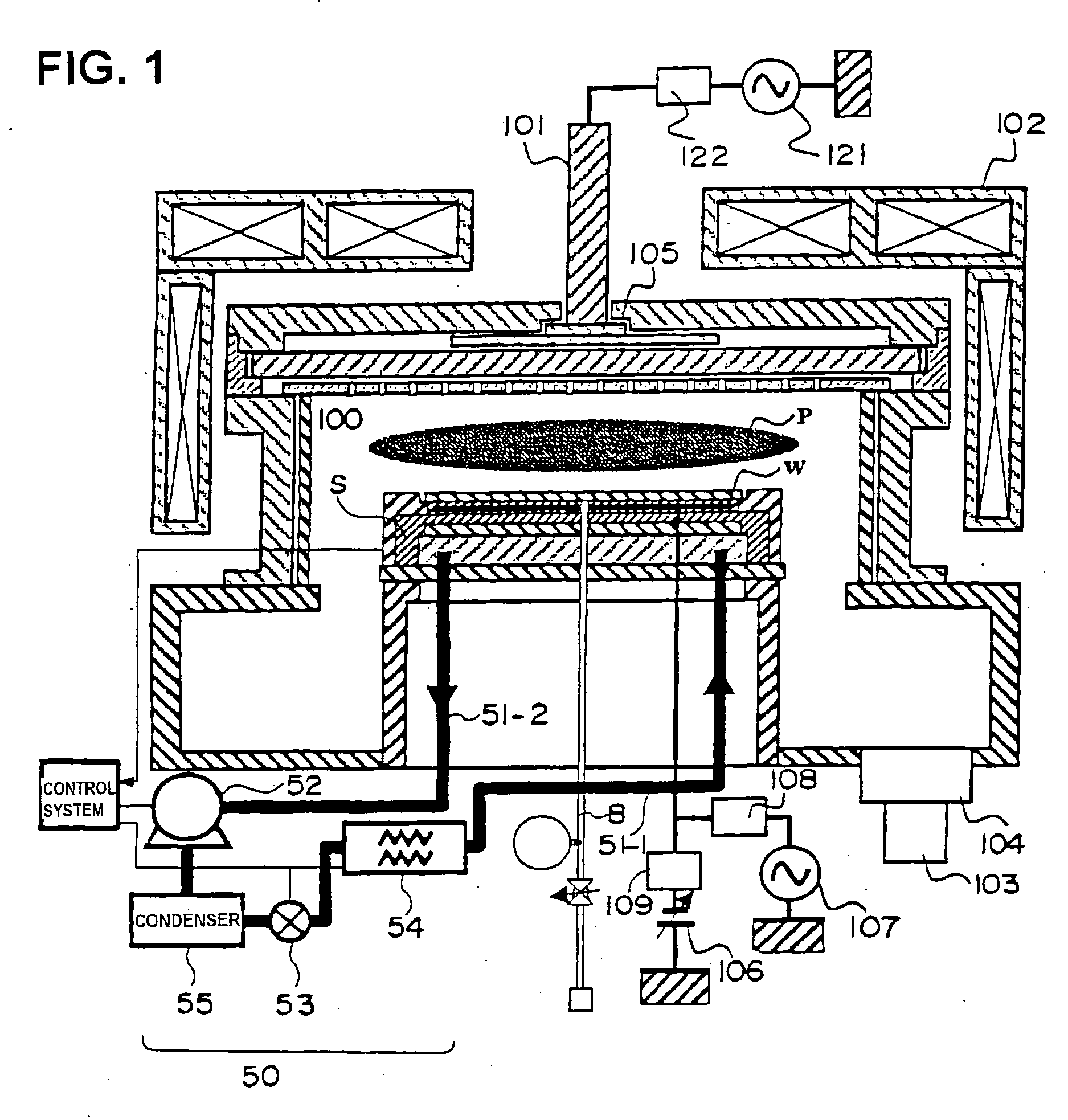
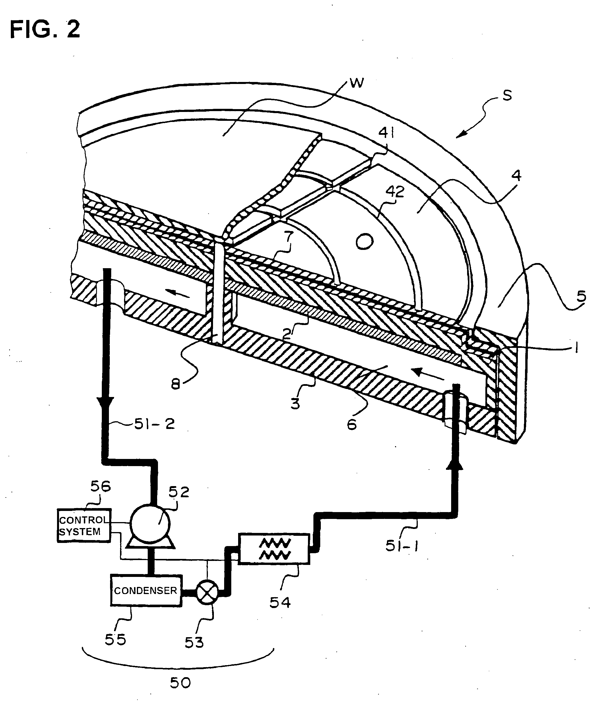
[0013] To solve the above problems, the present invention provides a plasma processing apparatus comprising: a holder stage comprising an electrode block having a dielectric film on the surface thereof and a coolant flow passage formed therein, for holding a semiconductor wafer on the dielectric film on the surface of the electrode block and performing temperature control; and a cooling cycle including a compressor, a condenser, an expansion valve and an evaporator; wherein the temperature control of the electrode block is performed by using a direct-expansion-type temperature controller in which the electrode block is used as the evaporator of the cooling cycle, and the coolant is directly circulated and expanded inside the electrode block.

Problems solved by technology

A temperature unit that circulates such a thermal medium can have small temperature variation owing to the thermal capacity of the circulated thermal medium itself, but can also have a poor temperature response.
Moreover, the temperature unit uses heat inefficiently since the temperature of the thermal medium is controlled via a heat exchanger, and it takes up large space since it requires a pump for circulating the thermal medium due to the apparatus configuration.
According to the above described conventional techniques, the temperature adjustment units for electrostatic chucking electrodes were not so adequately devised to achieve temperature control of a electrostatic chucking electrode with high efficiency and high accuracy.
As described above, for example, the temperature adjustment unit of patent Document 1 maintains the circulated thermal medium at a predetermined temperature via a heat exchanger in the thermal adjustment unit, and thus has poor thermal efficiency and requires a pump to circulate the thermal medium.
It also requires a large amount of thermal medium and has poor temperature response.
On the other hand, the method disclosed in patent Document 2 lacks to describe the detailed structure of an electrostatic chucking electrode.
For example, there is fear that the electrode block may deform into a convex shape when the coolant is directly circulated inside the electrostatic chucking electrode, due to the high pressure of the coolant.

Method used


Image

  • Plasma processing apparatus
  • Plasma processing apparatus
  • Plasma processing apparatus

Examples


Embodiment Construction

[0028] A plasma processing apparatus according to the present invention will be described in detail with reference to the drawings.

[0029] [Configuration of the Plasma Processing Apparatus]

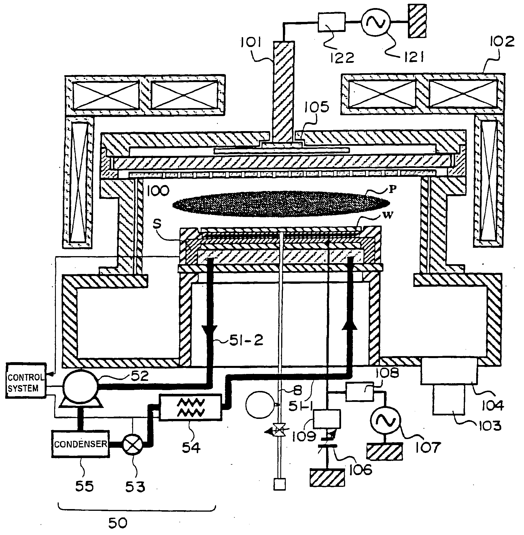
[0030]FIG. 1 is a cross-sectional view of a plasma processing apparatus of one embodiment of the present invention. The plasma processing apparatus in FIG. 1 comprises a processing chamber 100, an antenna 101 disposed above the processing chamber 100 for radiating electromagnetic waves, and a holder stage S for placing a workpiece such as a semiconductor wafer W, disposed at the lower area of the processing chamber 100. The antenna 101 is supported on a housing 105 formed as a part of a vacuum container, and is placed in parallel confronting relations to the holder stage S. On the periphery of the processing chamber 100 is provided magnetic field generation means 102 consisting of electromagnetic coils and yokes. The holder stage S is so-called an electrostatic chucking electrode, and will be thus...


PUM

PropertyMeasurementUnit
pressureaaaaaaaaaa
frequencyaaaaaaaaaa
frequencyaaaaaaaaaa

Abstract

A plasma processing apparatus having an electrostatic chucking electrode that allows temperature control of a semiconductor wafer during etching process with high efficiency comprises: a holder stage comprising an electrode block S having a dielectric film 4 on the surface thereof and a coolant flow passage 6 therein, in which temperature control is performed while holding a semiconductor wafer W on the dielectric film on the surface of the electrode block; and a cooling cycle 50 including a compressor 52, a condenser 55, an expansion valve 53, a heat exchanger 54 having a heater built therein, and an evaporator, wherein the temperature control of the electrode block S is performed by using a direct-expansion-type temperature controller in which the electrode block S is used as the evaporator of the cooling cycle, and the coolant is directly circulated and expanded inside the electrode block.

Description

BACKGROUND OF THE INVENTION [0001] 1. Field of the Invention [0002] The present invention relates to a plasma processing apparatus that is used in fine processing such as a semiconductor manufacturing process, and more particularly to a plasma processing apparatus comprising a holder stage for placing a semiconductor wafer. [0003] 2. Description of the Related Art [0004] Recent semiconductor integrated circuits that have more integrated features than ever have finer circuit patterns, and hence requires better accuracy in process dimension than ever. Moreover, measures are also required to increase throughputs and to process workpieces, such as semiconductor wafers, having larger sizes. Thus, higher electric power is required to be supplied to plasma processing apparatuses. In particular, in the case of a plasma processing apparatus for etching dielectrics, the electric power supplied during plasma generation tends to be increased so as to enhance the etching rate. Since most of the ...

Claims


Application Information

Patent Timeline
Patent Type & Authority Applications(United States)
IPC IPC(8): H01L21/00F25B1/00H01L21/3065
CPCH01J37/32082H01L21/67248H01L21/67109H01J2237/2001
Inventor ARAI, MASATSUGUUDO, RYUJIROKANNO, SEIICHIROYOSHIDA, TSUYOSHI
Owner HITACHI HIGH-TECH CORP
Learn More