Apparatus and method for friction stir welding using a consumable pin tool

a technology of friction stir welding and consumable pins, which is applied in the direction of welding apparatus, non-electric welding apparatus, manufacturing tools, etc., can solve the problems of warping and other dimensional defects in the workpiece, difficult joining of the type of weld joint, and geometric distortions near the welding joint. , to achieve the effect of improving the microstructure, improving the mechanical properties, and increasing the thickness of the weld join

Inactive Publication Date: 2005-03-03
GENERAL ELECTRIC CO
View PDF10 Cites 49 Cited by
  • Summary
  • Abstract
  • Description
  • Claims
  • Application Information

AI Technical Summary

Benefits of technology

[0009] Advantageously, the friction stir welding apparatuses and methods of the present invention provide a defect-free weld joint, without entrapped pin tool debris. As a result, the weld joint demonstrates improved mechanical properties (e.g., mechanical strength). Because, in one embodiment of the present invention, the filler material is the same as or similar to the workpiece material, the weld joint demonstrates improved microstructure. Because, in another embodiment of the present invention, the filler material is dissimilar from the workpiece material, the mater...

Problems solved by technology

Likewise, other conventional joining techniques may create geometric distortions near a weld joint due to high temperature gradients induced in a workpiece during welding.
These distortions may cause warping and other dimensional defects in the workpiece, as well as residual stresses that may cause premature failure by cracking in the heat-affected zone or weld joint, lamellar tearing, or by stress-corrosion cracking in some metals and metal alloys.
In addition, some metals, metal alloys, other materials, an...

Method used


Image

  • Apparatus and method for friction stir welding using a consumable pin tool
  • Apparatus and method for friction stir welding using a consumable pin tool
  • Apparatus and method for friction stir welding using a consumable pin tool

Examples


Embodiment Construction

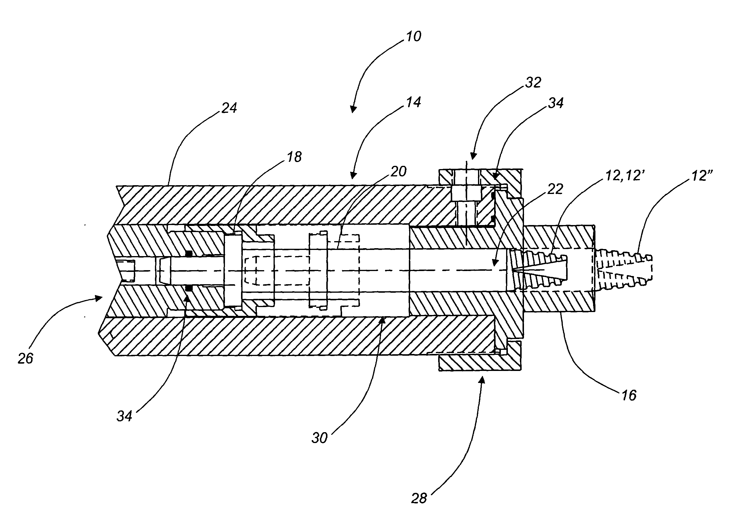
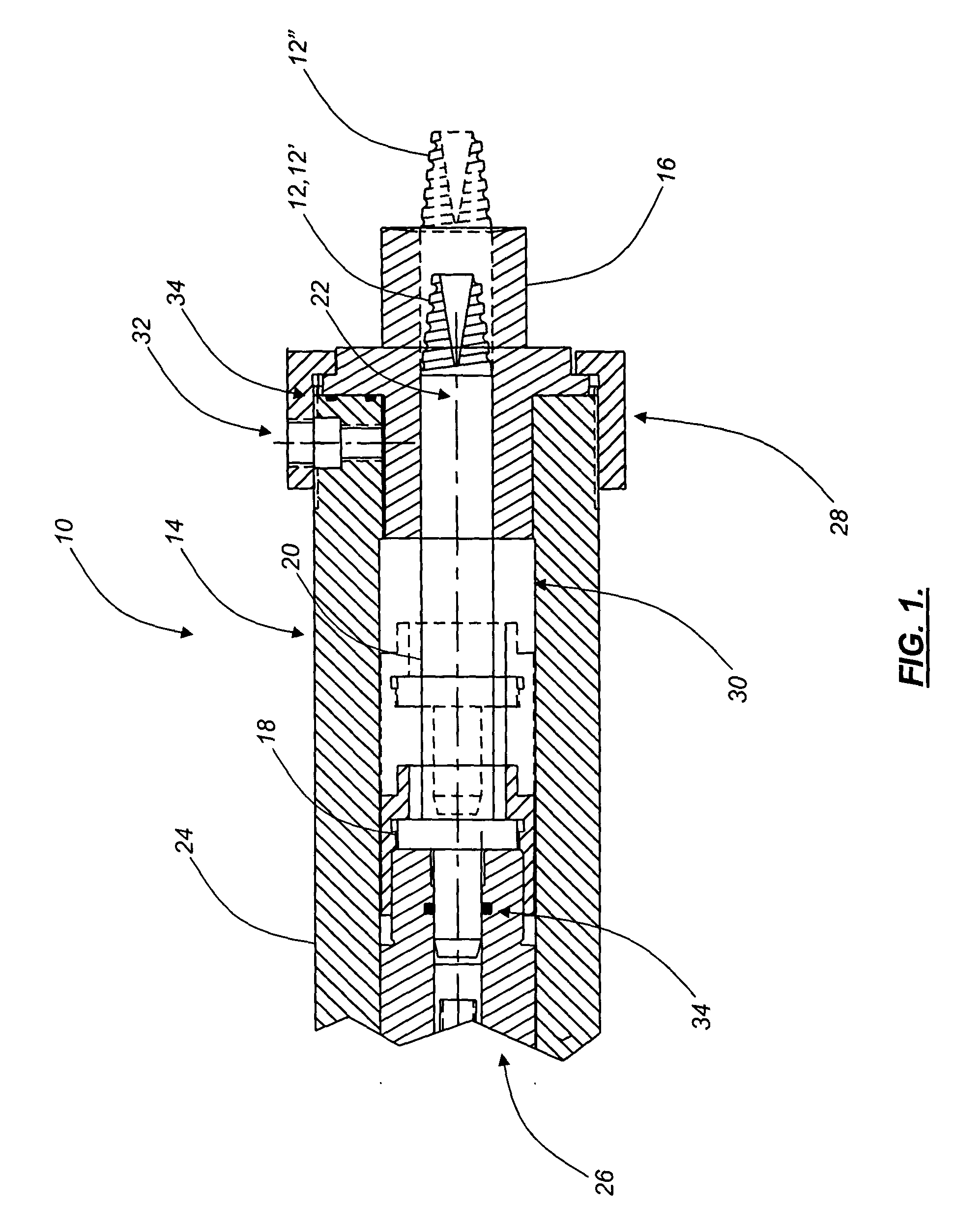
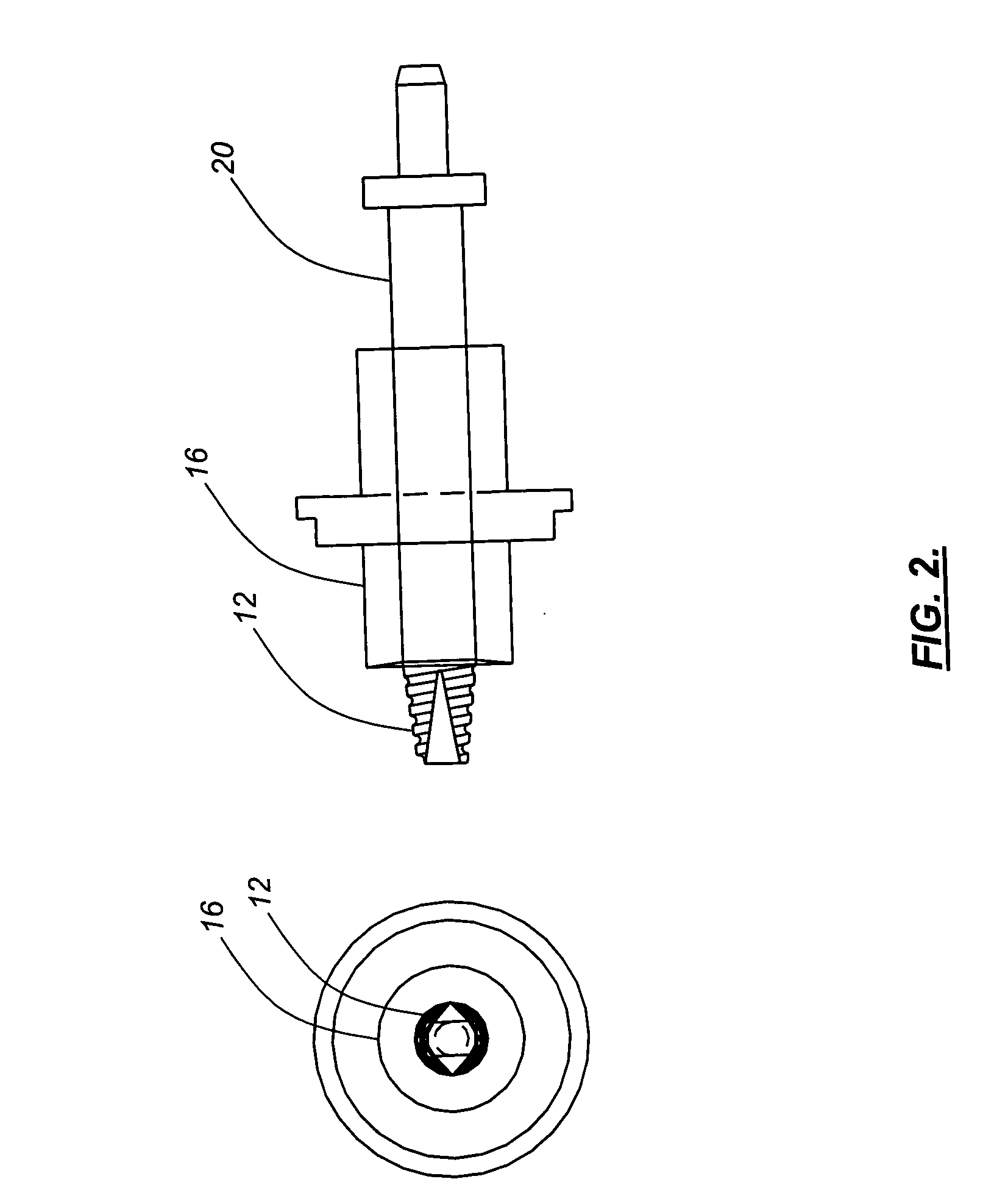
[0017] Referring to FIGS. 1 and 2, in one embodiment, the friction stir welding apparatus 10 of the present invention includes a consumable pin tool 12 that is selectively disposed within a pin tool holder 14. The pin tool 12 is selectively and continuously movable between a first, retracted position 12′ and a second, extended position 12″. In the second, extended position 12″, the pin tool 12 at least partially protrudes beyond the surface of a shoulder 16 associated with the pin tool 12 and the pin tool holder 14. Preferably, the pin tool 12 has a substantially cylindrical, rod-like, or conical shape. For example, the pin tool 12 may have a substantially pointed shape with a taper of about 45 degrees. Optionally, the pin tool 12 is threaded and / or incorporates one or more sharp edges and / or flat surfaces. The pin tool 12 may also be partially or wholly hollow. In the substantially cylindrical or rod-like configuration, the initial diameter and length of the pin tool 12, before bei...


PUM

PropertyMeasurementUnit
Diameteraaaaaaaaaa
Feed rateaaaaaaaaaa
Volumeaaaaaaaaaa

Abstract

The present invention provides a friction stir welding apparatus operable for welding one or more metals, metal alloys, or other materials. The friction stir welding apparatus includes a pin tool holder, a shoulder having a surface coupled to the pin tool holder, and a pin tool coupled to the pin tool holder, the pin tool at least partially protruding from the surface of the shoulder, wherein the pin tool is made of a consumable pin tool material. Optionally, the shoulder rotates at a predetermined rotational speed and is retractable into/extendable from the pin tool holder at a substantially constant rate. Optionally, the shoulder is also made of a consumable shoulder material that is at least partially incorporated into the volume of a joint to be welded. The consumable shoulder material comprises a material that is the same as, similar to, or dissimilar from one or more materials comprising a workpiece to be friction stir welded. Preferably, the pin tool rotates at a predetermined rotational speed and is retractable into/extendable from the surface of the shoulder at a substantially constant rate. The consumable pin tool material is at least partially incorporated into the volume of the joint to be welded. The consumable pin tool material comprises a material that is the same as, similar to, or dissimilar from one or more materials comprising the workpiece to be friction stir welded.

Description

FIELD OF THE INVENTION [0001] The present invention relates generally to an apparatus and a method for friction stir welding. More specifically, the present invention relates to an apparatus and a method for friction stir welding using a consumable pin tool. BACKGROUND OF THE INVENTION [0002] Friction stir welding is a solid-state joining technique that is well known to those of ordinary skill in the art. Typically, friction stir welding is used to join difficult-to-weld metals, metal alloys (such as aluminum alloys, titanium alloys, nickel alloys, and the like), and other materials. For example, certain aluminum alloys are sensitive in a plasticized heat-affected zone, where the base metal reaches temperatures between solidus and liquidus during welding. In this zone, partial melting at grain boundaries forms a network containing brittle compounds. As a result, weld ductility is substantially reduced. Likewise, other conventional joining techniques may create geometric distortions ...

Claims


Application Information

Patent Timeline
IPC IPC(8): B23K20/12
CPCB23K20/1215B23K20/128B23K20/1255B23K20/125
Inventor SUBRAMANIAN, PAZHAYANNUR RAMANATHANHELDER, EARL CLAUDETRAPP, TIMOTHY JOSEPH
Owner GENERAL ELECTRIC CO
Why Eureka
Try Eureka