Non-dispersive charged particle energy analyzer

a charged particle and energy analyzer technology, applied in the direction of beam deviation/focusing by electric/magnetic means, instruments, heat measurement, etc., can solve the problems of limited spatial and angular acceptance of electrons, large and heavy weight of diffuse electron energy analyzers, and limited use of energy resolution and stability

Inactive Publication Date: 2005-03-03
BRYSON III CHARLES E
View PDF2 Cites 98 Cited by
  • Summary
  • Abstract
  • Description
  • Claims
  • Application Information

AI Technical Summary

Problems solved by technology

However, dispersive electron energy analyzers tend to be large and heavy, having a diameter of 1 m and a volume of 0.5 m3.
In addition, they generally have a limited spatial and angular acceptance for electrons coming from a material surface.
However, their energy resolution and stability have limited their use.
It also has a high throughput, but the collection efficiency of the analyzer must be compromised considerably to achieve good energy resolution.

Method used


Image

  • Non-dispersive charged particle energy analyzer
  • Non-dispersive charged particle energy analyzer
  • Non-dispersive charged particle energy analyzer

Examples


Embodiment Construction

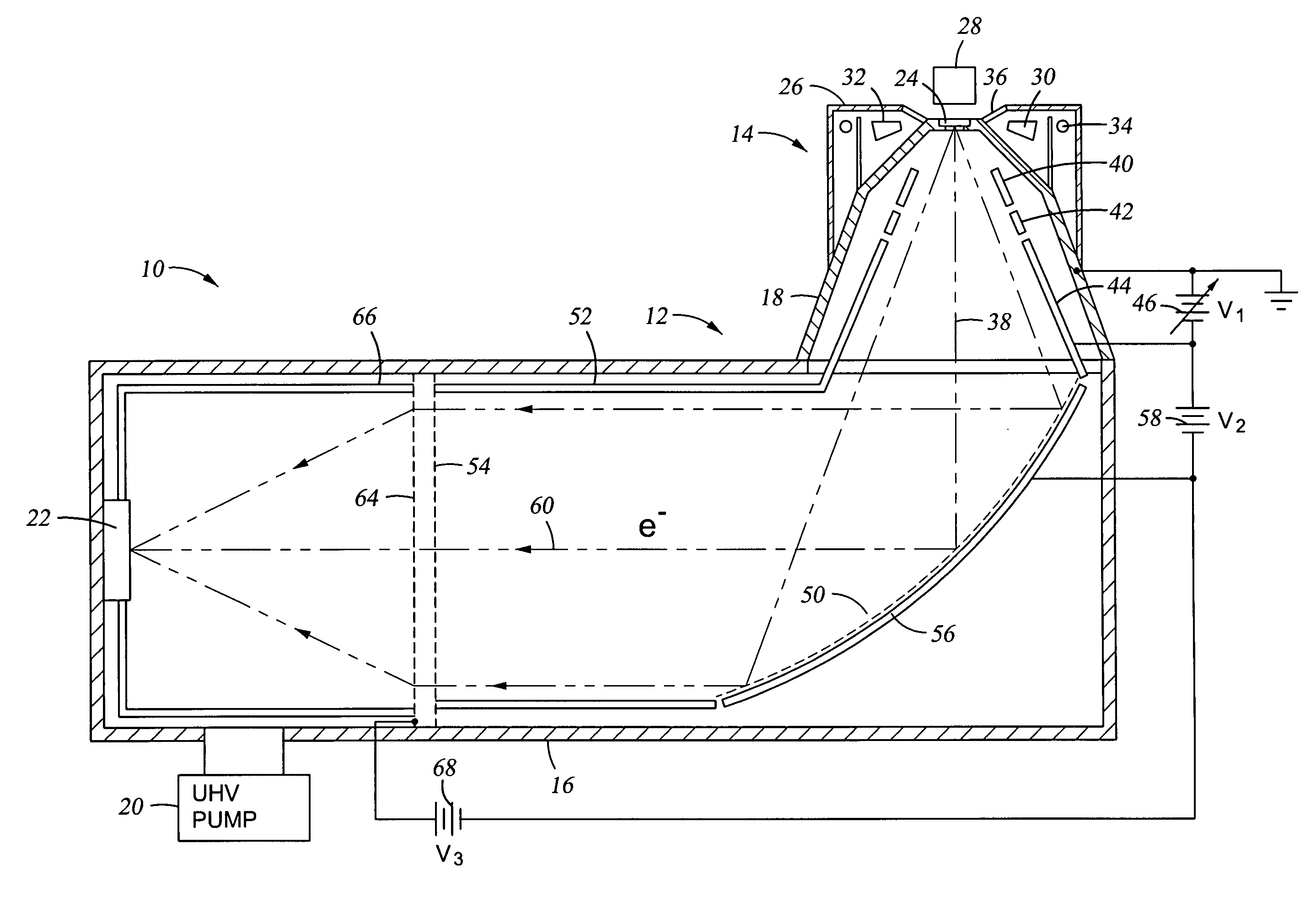
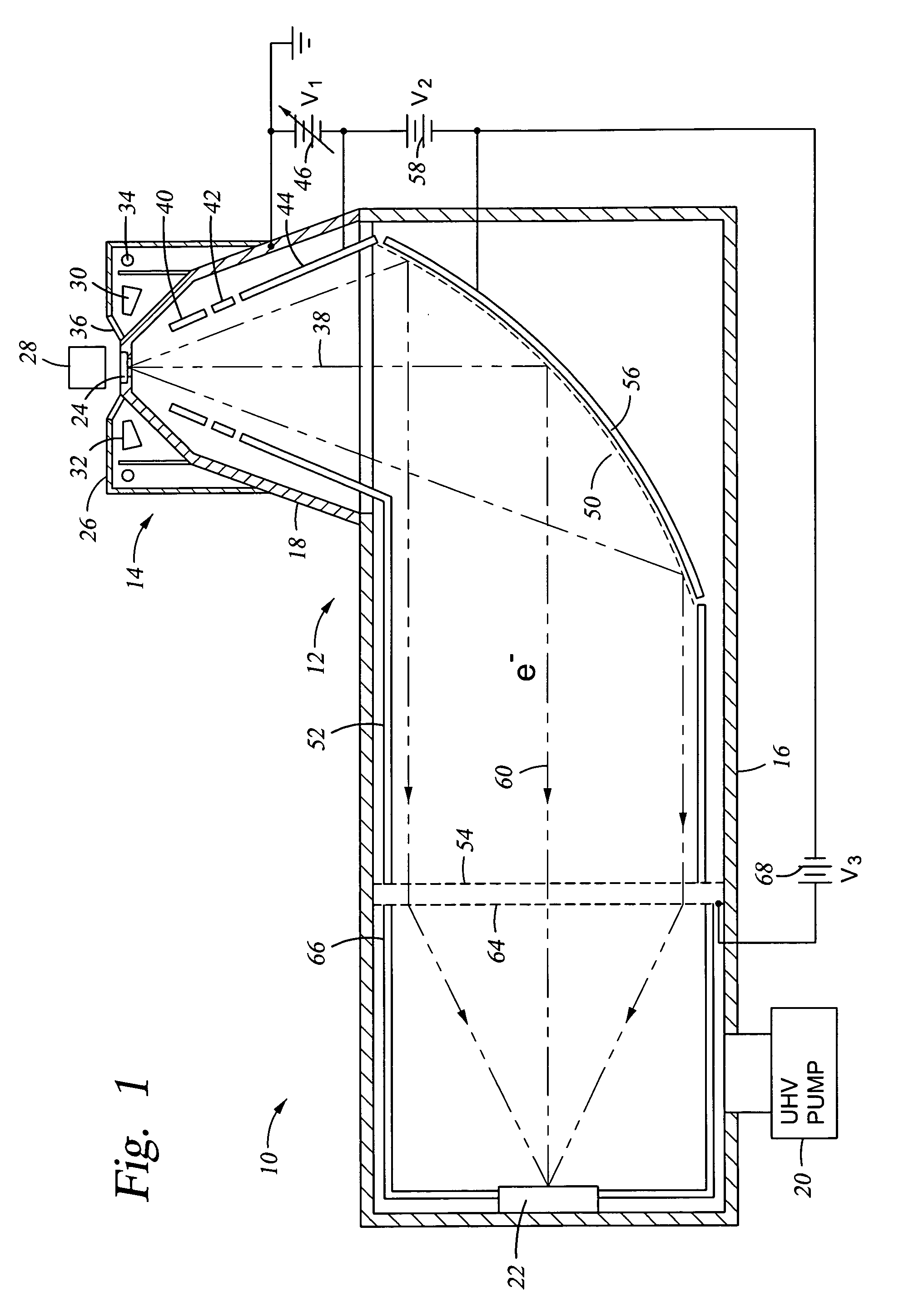
[0024] A compact X-ray photoelectron spectrometer (XPS) 10, illustrated in cross section in FIG. 1, includes a compact and rugged electron energy analyzer 12 of the invention and an electron source 14. The energy analyzer 12 includes a tubular main chamber 16 extending along a main chamber axis and having a diameter of about 10 cm and a generally conically shaped side chamber 18 extending along a source axis inclined to the main chamber axis and disposed at one end of the main chamber 16. The side chamber 18 supports the electron source 14. Both the main chamber 16 and the side chamber 18 are vacuum pumped to UHV pressure by a vacuum pump system 20 sufficiently low that the mean free path of the electrons being measured is significantly longer than the total path length within the two chambers 16, 18. It is assumed that both chambers 16, 18 are conductive and electrically grounded. An electron detector 22, such as a microchannel plate or photomultiplier tube, is disposed on the othe...


PUM


Abstract

An electron energy analyzer including a curved electrostatic low-pass reflector and a high-pass electrostatic transmissive filter. The reflector comprises a curved grid, preferably ellipsoidal, and an absorber electrode placed in back of the curved grid with respect to the electron source and biased negatively to the curved grid to act as a reflective low-pass filter and a collimating optics for the reflected beam. The transmissive filter includes first and second flat grids extending across the collimated reflected beam. The second grid on the side of the first grid opposite the curved grid is biased negatively to the first grid and the absorber electrode. A field free region is created by applying the same bias to the curved grid, the first grid, and chamber sidewall sleeve. An electron detector detects all electrons passed by the second grid in an energy band in the overlap of the high-pass and low-pass bands.

Description

RELATED APPLICATION [0001] This application is a continuation in part of Ser. No. 10 / 618,078, filed Jul. 11, 2003 and scheduled to issue on Oct. 12, 2004 as U.S. Pat. No. 6,803,570.BACKGROUND OF THE INVENTION [0002] 1. Field of the Invention [0003] The invention relates generally to analyzers for charged particle beams. In particular, the invention relates to energy analyzers of electrons or other charged particles. [0004] 2. Background Art [0005] The parent application Ser. No. 10 / 618,078, incorporated herein by reference in its entirety, describes a spectrometer in which the energy of secondary electrons is measured in the range of a few electron volts (eV) to a few keV. There are many types of such spectrometers used for characterizing the composition and other properties of materials in which the electron energy needs to be measured, for example, X-ray photoelectron spectrometers and electron spectrometers, and secondary ion spectrometers. Similar spectroscopes, such as secondar...

Claims


Application Information

Patent Timeline
Patent Type & Authority Applications(United States)
IPC IPC(8): G01Q30/16H01J3/26H01J33/04H01J37/252
CPCH01J33/04H01J37/05H01J37/244H01J49/488H01J2237/2448H01J2237/24485H01J3/26
Inventor KELLY, MICHAEL A.BRYSON, CHARLES E. III
Owner BRYSON III CHARLES E
Why Eureka
Try Eureka