Claw-pole type stepping motor

Inactive Publication Date: 2005-03-03
MINEBEA CO LTD
View PDF4 Cites 21 Cited by
  • Summary
  • Abstract
  • Description
  • Claims
  • Application Information

AI Technical Summary

Benefits of technology

[0006] The present invention has been made in light of the above circumstances, and it is an object of the present invention to overcome the difficulty in resin-moldi

Problems solved by technology

In such a claw-pole type stepping motor, the diameter of a rotor magnet is restricted by the inner diameter of a stator, so a motor with a smaller dimension is forced to have a rotor magnet with a smaller diameter thus resulting in significant deterioration in motor characteristic.
This makes it difficult for a claw-pole type stepping motor with a small radial dimension to ensure performance characteristic required for poisoning control.
In such a case, a brushless DC motor equipped with an encoder as a position detector must be used in place of a claw-pole type stepping motor, which inevitably pushes up production cost.
A ca

Method used


Image

  • Claw-pole type stepping motor
  • Claw-pole type stepping motor
  • Claw-pole type stepping motor

Examples


Embodiment Construction

[0022] An embodiment of the present invention will hereinafter be described with reference to the accompanying drawings.

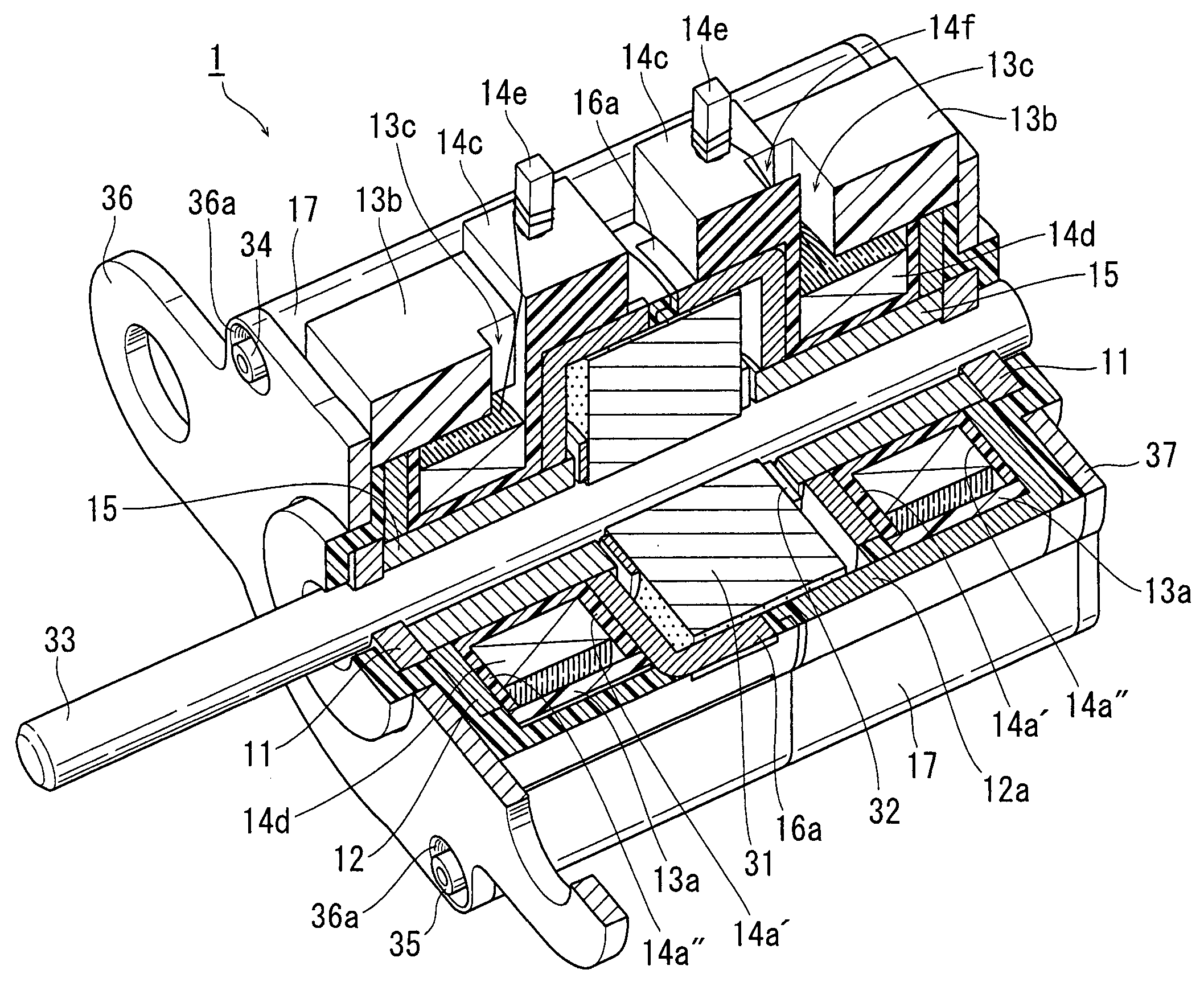
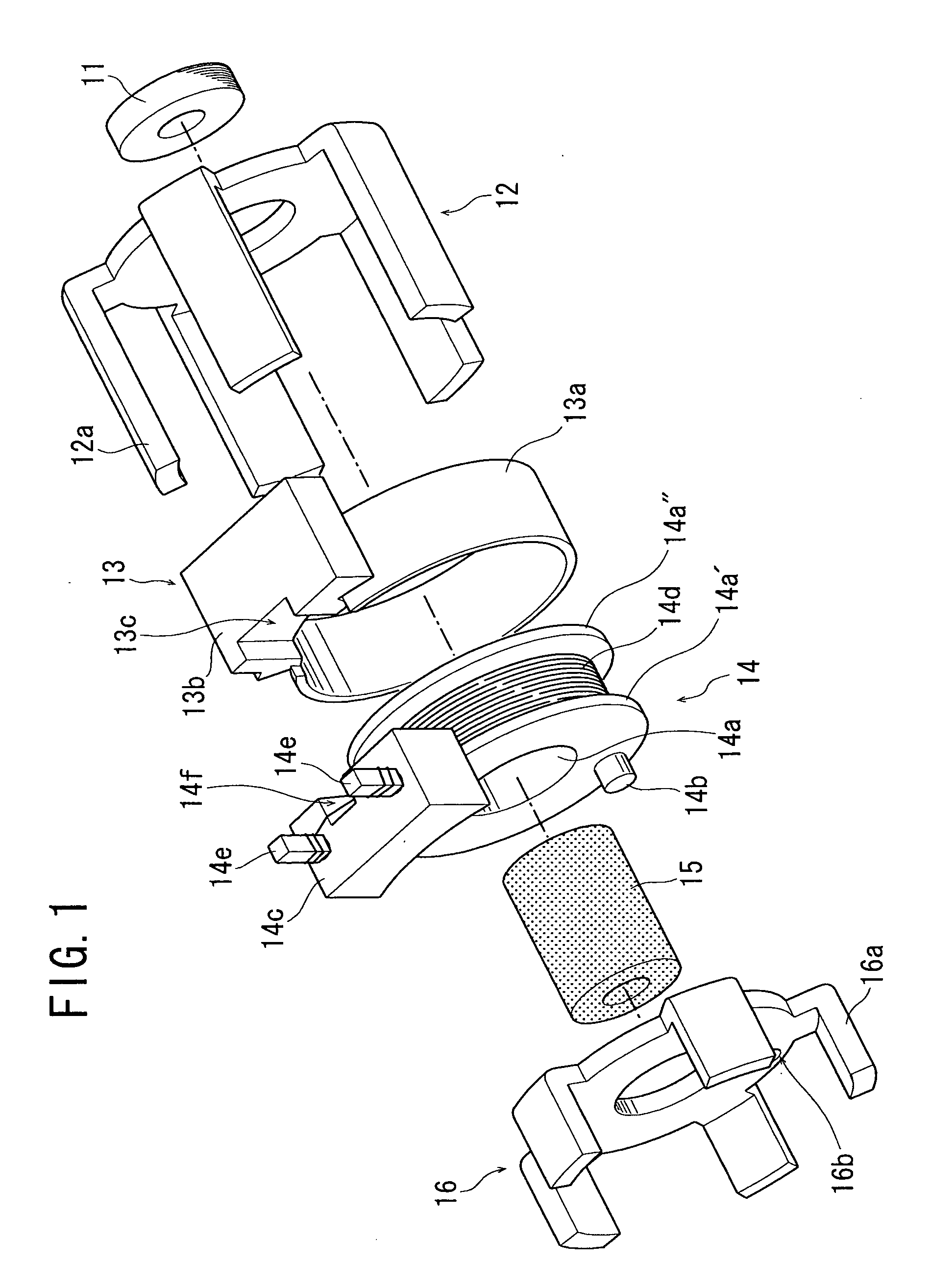
[0023] A stepping motor according to the present invention comprises two stator units, specifically an A-phase stator unit and a B-phase stator unit arranged coaxially to each other. The B-phase stator unit is shown in FIG. 1 in an exploded manner so as to explain its constituent parts. The A-phase stator unit uses common constituent parts to the B-phase stator unit and an explanation thereof will be omitted. Since the A-phase and B-phase stator units use common constituent parts, the production cost of the parts can be reduced.

[0024] Referring to FIG. 1, the B-phase stator includes a bearing 11, a first stator yoke 12, a cover ring 13, a bobbin 14, a core 15, and a second stator yoke 16.

[0025] The bearing 11 is, for example, a sintered sleeve bearing to rotatably support a rotary shaft of a rotor assembly to be described later.

[0026] The first and second stato...


PUM


Abstract

A claw-pole type stepping motor comprises: a rotor assembly shaped substantially cylindrical, and having a center shaft; and a stator assembly composed of two cup-shaped stator units which are coupled to each other coaxially so as to axially sandwich the rotor assembly, and which each include a bobbin having a magnet wire wound therearound, and two pole tooth arrays magnetically connected to each other and shifted in phase from each other by an electrical angle of 180 degrees. In the motor, each stator unit further includes a cover ring which protects the magnet wire wound around the bobbin against resin injected when the stator unit is resin-molded for an integrated solid structure. The motor structured as described above can be successfully resin-molded so as to enable elimination of a motor case, thus achieving downsizing for the dimension of the eliminated motor case while maintaining a sufficient mechanical strength.

Description

BACKGROUND OF THE INVENTION [0001] 1. Field of the Invention [0002] The present invention relates to a structure of a claw-pole type stepping motor, and particularly to a structure thereof for achieving reduction in dimension and offering technical advantages. [0003] 2. Description of the Related Art [0004] As various electronic devices are increasingly requested to be downsized, motors incorporated in the devices are also requested to be downsized. In a conventional claw-pole type stepping motor with an inner rotor, A-phase and B-phase driving coils are typically disposed so as to surround the outer circumference of a rotor. In such a claw-pole type stepping motor, the diameter of a rotor magnet is restricted by the inner diameter of a stator, so a motor with a smaller dimension is forced to have a rotor magnet with a smaller diameter thus resulting in significant deterioration in motor characteristic. This makes it difficult for a claw-pole type stepping motor with a small radial ...

Claims


Application Information

Patent Timeline
IPC IPC(8): H02K1/14H02K3/52H02K5/00H02K5/15H02K5/22H02K37/12H02K37/14
CPCH02K1/145H02K3/525H02K5/00H02K37/14H02K5/225H02K37/125H02K5/15
Inventor MATSUSHITA, KUNITAKEYAMAWAKI, TAKAYUKINAGATA, TOSHIHIKO
Owner MINEBEA CO LTD
Why Eureka
Try Eureka