Liquid jet head and liquid jet apparatus

a liquid jet and apparatus technology, applied in printing and other directions, can solve the problems of difficult miniaturization of the head, difficult high-density arrangement, complex manufacturing process, etc., and achieve the effect of improving the quality of printing

Active Publication Date: 2005-03-03
SEIKO EPSON CORP
View PDF3 Cites 24 Cited by
  • Summary
  • Abstract
  • Description
  • Claims
  • Application Information

AI Technical Summary

Benefits of technology

[0018] In the fifth aspect, printing quality is improved

Problems solved by technology

However, there is a problem that the manufacturing process is complex for the following reason: this type requires a difficult process of cutting piezoelectric elements into a comb-like shape so as to match the piezoelectric elements with the arrangement pitch of nozzle orifices, and also work of fixing the cut piezoelectric elements while positioning them to the pressure generating chambers.
However, there is a problem that a certain area is needed because of the utilization of flexural vibration and that high-density arrangement is difficult.
However, since the penetrated holes are

Method used


Image

  • Liquid jet head and liquid jet apparatus
  • Liquid jet head and liquid jet apparatus
  • Liquid jet head and liquid jet apparatus

Examples


embodiment 1

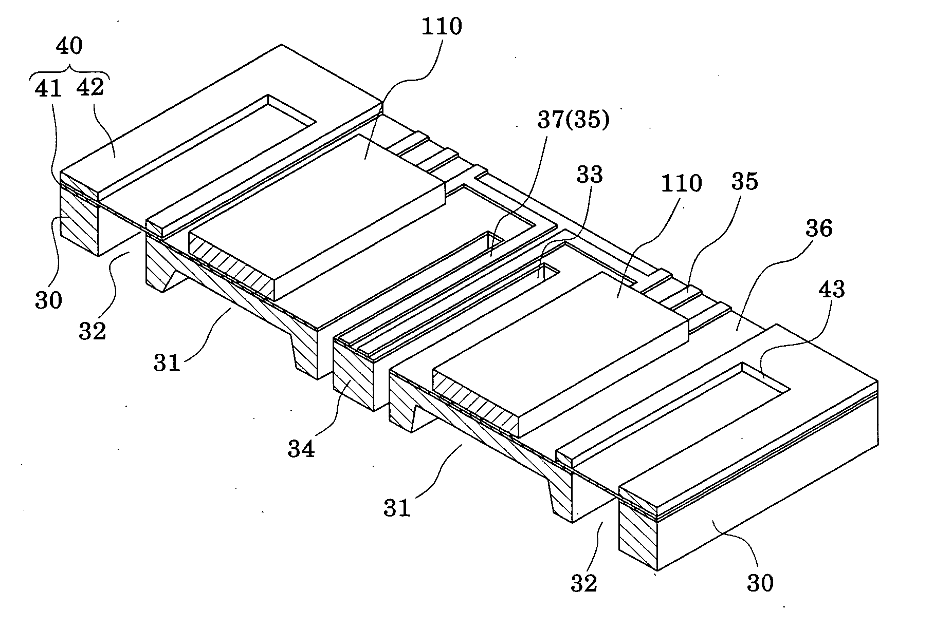
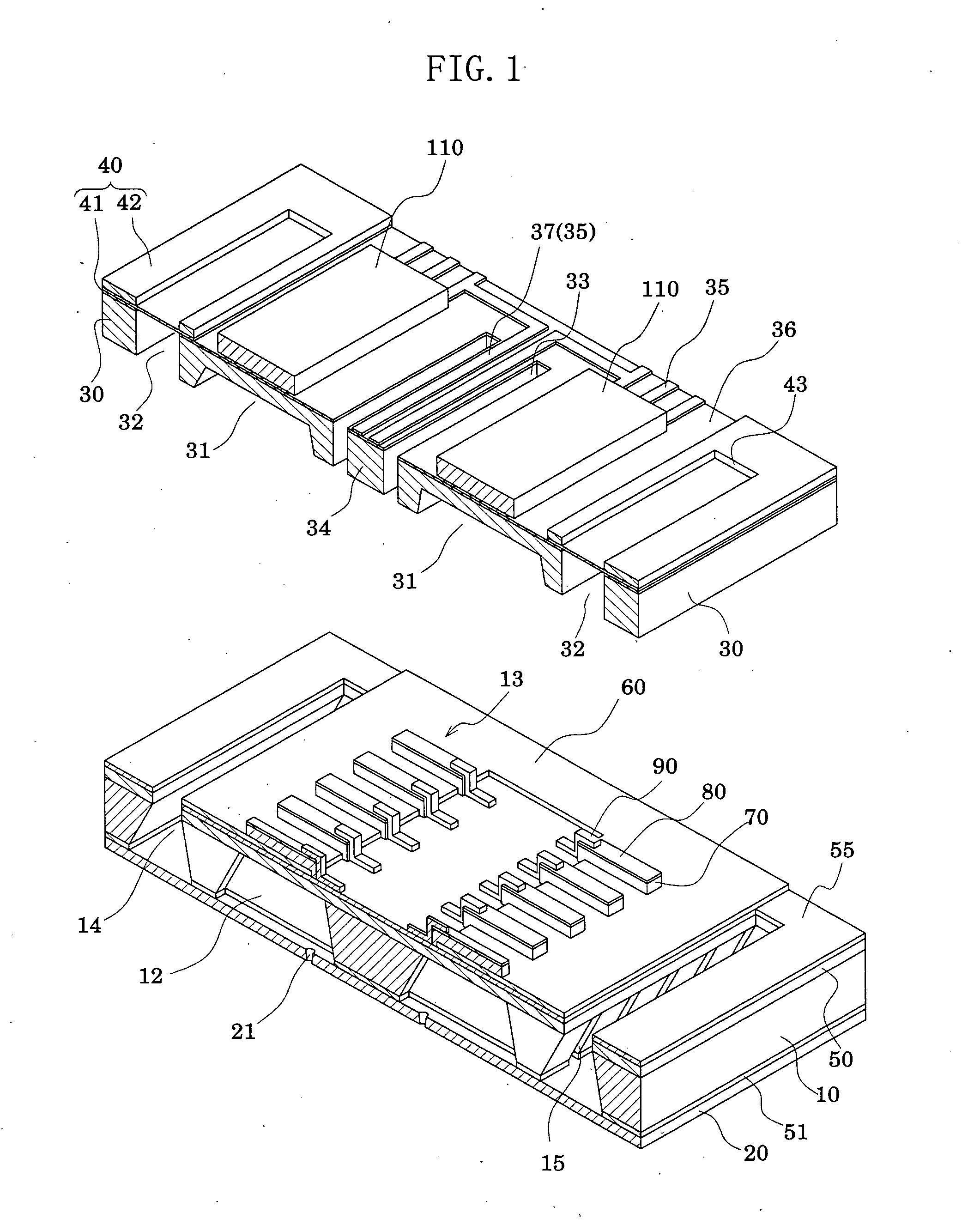
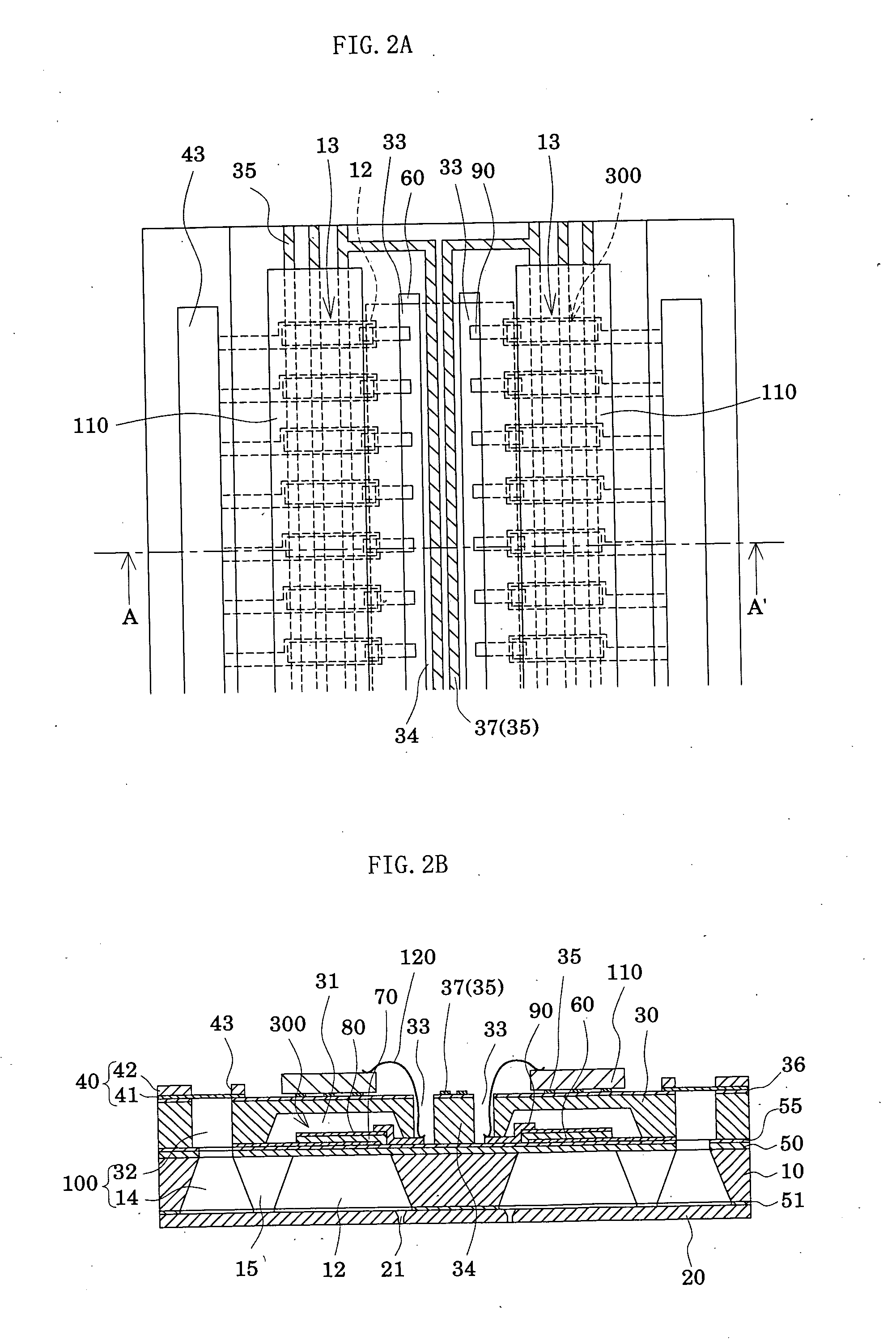
[0024]FIG. 1 is an exploded perspective view showing an ink jet recording head according to Embodiment 1 of the present invention. FIGS. 2A and 2B are a plan view and a cross-sectional view of FIG. 1, respectively. As shown in these drawings, in the present embodiment, a passage-forming substrate 10 is made of a single crystal silicon substrate with (110) plane orientation. An elastic film 50 which is made of silicon dioxide previously formed by thermal oxidation and which has a thickness of 1 to 2 μm, is formed on one surface of the passage-forming substrate 10. Two rows 13 each of which has a plurality of pressure generating chambers 12 arranged in a row in the width direction thereof, are formed in the passage-forming substrate 10. Moreover, communicating portions 14 are formed in the passage-forming substrate 10, in regions outside the pressure generating chambers 12 in the longitudinal direction thereof. The communicating portions 14 and the pressure generating chambers 12 are ...

embodiments 2

[0039]FIG. 3 is a plan view of an ink jet recording head according to Embodiment 2. As shown in FIG. 3, in the present embodiment, two penetrated holes 33A and 33B are provided for each row 13 of the pressure generating chambers 12, and a beam portion 34A is also formed between the two penetrated holes 33A and 33B. That is, in the present embodiment, two driving ICs 110A and 110B are mounted on the sealing plate 30, in each of the regions facing the rows 13 of the pressure generating chambers 12, and thus four driving ICs 110 in total are mounted. The present embodiment is the same as Embodiment 1, except that the penetrated holes 33A and 33B are provided for the respective driving ICs 110 and that the beam portion 34A is formed between each pair of the two penetrated holes 33A and 33B to be integrated with the sealing plate 30 using the same member thereof.

[0040] Such a structure also provides the same effects as Embodiment 1. Moreover, forming the beam portions 34A makes it possi...


PUM


Abstract

A liquid jet head includes: a passage-forming substrate provided with at least two rows of pressure generating chambers each communicating with a nozzle orifice; and piezoelectric elements for causing pressure change in the pressure generating chambers. The piezoelectric elements are provided on one side of the passage-forming substrate with a vibration plate interposed therebetween. On a joint plate joined to the piezoelectric element side of the passage-forming substrate, driving ICs for driving the piezoelectric elements are provided in regions facing the respective rows of the pressure generating chambers. For each row of the pressure generating chambers, at least one penetrated hole, in which lead electrodes led from the piezoelectric elements are exposed, is provided in a region of the joint plate, the region corresponding to a region between the rows of the pressure generating chambers. A beam portion is formed between the adjacent penetrated holes.

Description

FIELD OF THE INVENTION [0001] The present invention relates to a liquid jet head and a liquid jet apparatus. The present invention particularly relates to an ink jet recording head and an ink jet recording apparatus wherein part of pressure generating chambers communicating with nozzle orifices for ejecting ink droplets are constituted of a vibration plate; piezoelectric elements are formed on a surface of the vibration plate; ink droplets are ejected using the displacement of the piezoelectric elements. BACKGROUND OF THE INVENTION [0002] For ink jet recording heads in which part of pressure generating chambers communicating with nozzle orifices for ejecting ink droplets are constituted of a vibration plate and in which the vibration plate is deformed by piezoelectric elements to apply pressure to ink in the pressure generating chambers and thereby to eject ink droplets from the nozzle orifices, two types of ink jet recording heads are in practical use. One uses a longitudinal vibra...

Claims


Application Information

Patent Timeline
IPC IPC(8): B41J2/045B41J2/055B41J2/14
CPCB41J2/14233B41J2002/14491B41J2002/14419B41J2002/14241B41J2/045
Inventor OWAKI, HIROSHIGEMIYATA, YOSHINAO
Owner SEIKO EPSON CORP
Why Eureka
Try Eureka