CDMA receiving apparatus, method, program and recording medium

a technology of cdma and receiving apparatus, applied in the direction of electrical apparatus, digital transmission, radio transmission, etc., can solve the problems of inability to perform demodulation adaptation to the abruptly changed receiving environment, inability to determine the cell selection, and difficulty in discriminating between signal power and noise power peaks, so as to improve the reception error characteristics

Inactive Publication Date: 2005-03-03
SHARP KK
View PDF4 Cites 33 Cited by
  • Summary
  • Abstract
  • Description
  • Claims
  • Application Information

AI Technical Summary

Benefits of technology

[0020] It is an object of the present invention to improve the reception error characteristics. The object of the present invention is accomplished as follows: There is provided a received signal wave-form buffer unit which is capable of recording received signal wave-form data in which the amplitude of the received signal wave-form is digitalized on different recording areas for each unit processing length. A delay profile which represents the signal power distribution relative to the delay time on a path is generated by multiplying said received signal wave-form data by a demodulation code and determining a sum for a time interval which is given as a desired constraint length. The timing position at which the signal power peaks is determined as a path candidate used for signal demodulation based upon the generated delay profile. A plurality of demodulation paths which is as many as the number of predetermined demodulation paths are selected from said path candidates. After each demodulation symbol of demodulation path is demodulated by using the same received signal wave-form data recorded on the received signal wave-form buffer unit, the symbol phases of the demodulation symbol of each demodulation path are aligned so that the symbols are RAKE combined to provide a combined demodulation symbol. The combination of said demodulation paths is charged depending upon the error rate of the combined demodulation symbols. A demodulation operation for outputting the combined demodulation symbol for the same received signal wave-form data is repeated to improve the reception error characteristics.
[0021] There is provided a wake-up counter for counting the wake-up timings which is substantially synchronized with the stand-by information reception timing when the stand-by information is received. With the wake-up timing, the power to the radio unit and received signal wave-form buffer unit is turned on to record the received signal wave-form data on the stand-by information for a period of time required for channel detection of stand-by information and / or peripheral cells. After completion of recording, the power to the radio unit is turned off and then a channel demodulation related with stand-by information is conducted and the power to each circuit unit for channel detection related with peripheral cells is turned on. The power to each circuit unit other than the wake-up counter is turned off when the channel demodulation and / or channel detection operation is completed, so that reduction in power consumption is achieved.

Problems solved by technology

The prior art receiving apparatus which determines the timing which represents the peak power value by consecutively averaging the signal levels is not capable of following abrupt change in signal level if the receiving environment abruptly changes so that channel estimating result changes.
There is a strong likelihood that demodulation which is adapted to the abruptly changed receiving environment and determination for cell selection can not be conducted.
If the condition of the electromagnetic waves which are being received deteriorates for the prior art receiving apparatus which conducts a demodulation operation independently of the receiving condition, it would be difficult to discriminate between the signal power and noise power peaks.
The error rate of the demodulated symbol is also deteriorated by the amount of the deleted signals.
In other words, use of erroneous peak (noise power peak) which is not the signal power peak is used for the demodulation path will deteriorate the error rate of the demodulated symbol.
Therefore, this may result in that the processing burden becomes heavier and much power is consumed due to the fact that the length of constraint is longer than required.
This invites an increase in power consumption.
This invites an increase in cost of the receiving apparatus.
Therefore, if the receiving condition deteriorates, the possibility to detect the signal power peak related with the stand-by information as well as the power peak caused by noise as demodulation path becomes higher, so that selection of an erroneous path is inevitable on reception of the stand-by path.
The error rate of the demodulation result relating to the stand-by information will deteriorate.
Therefore, this may result in that the processing burden becomes heavier and much power is consumed due to the fact that the length of constraint is longer than required.
Accordingly, the circuit scale becomes larger and the cost of the receiving apparatus increases.

Method used


Image

  • CDMA receiving apparatus, method, program and recording medium
  • CDMA receiving apparatus, method, program and recording medium
  • CDMA receiving apparatus, method, program and recording medium

Examples


Embodiment Construction

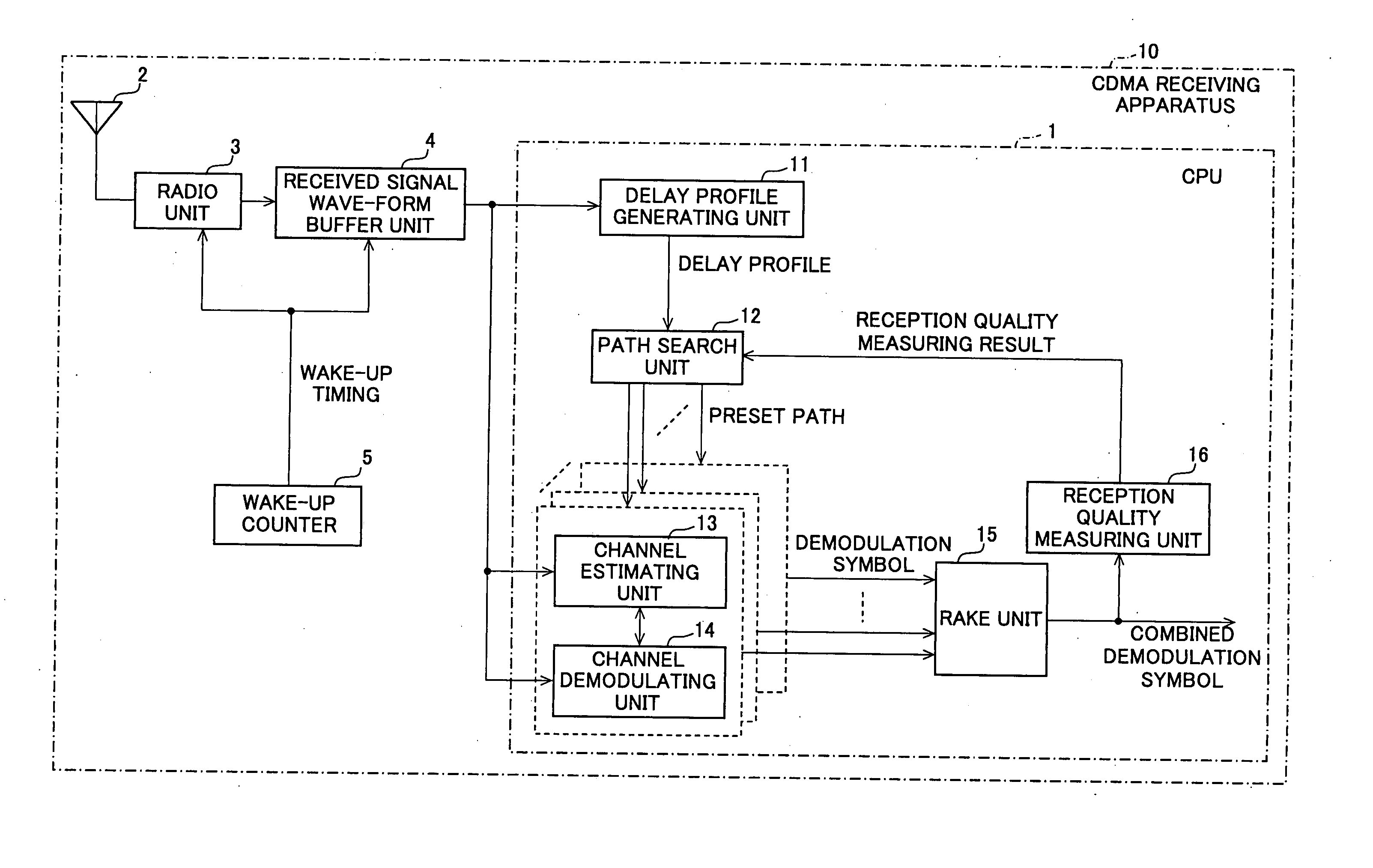
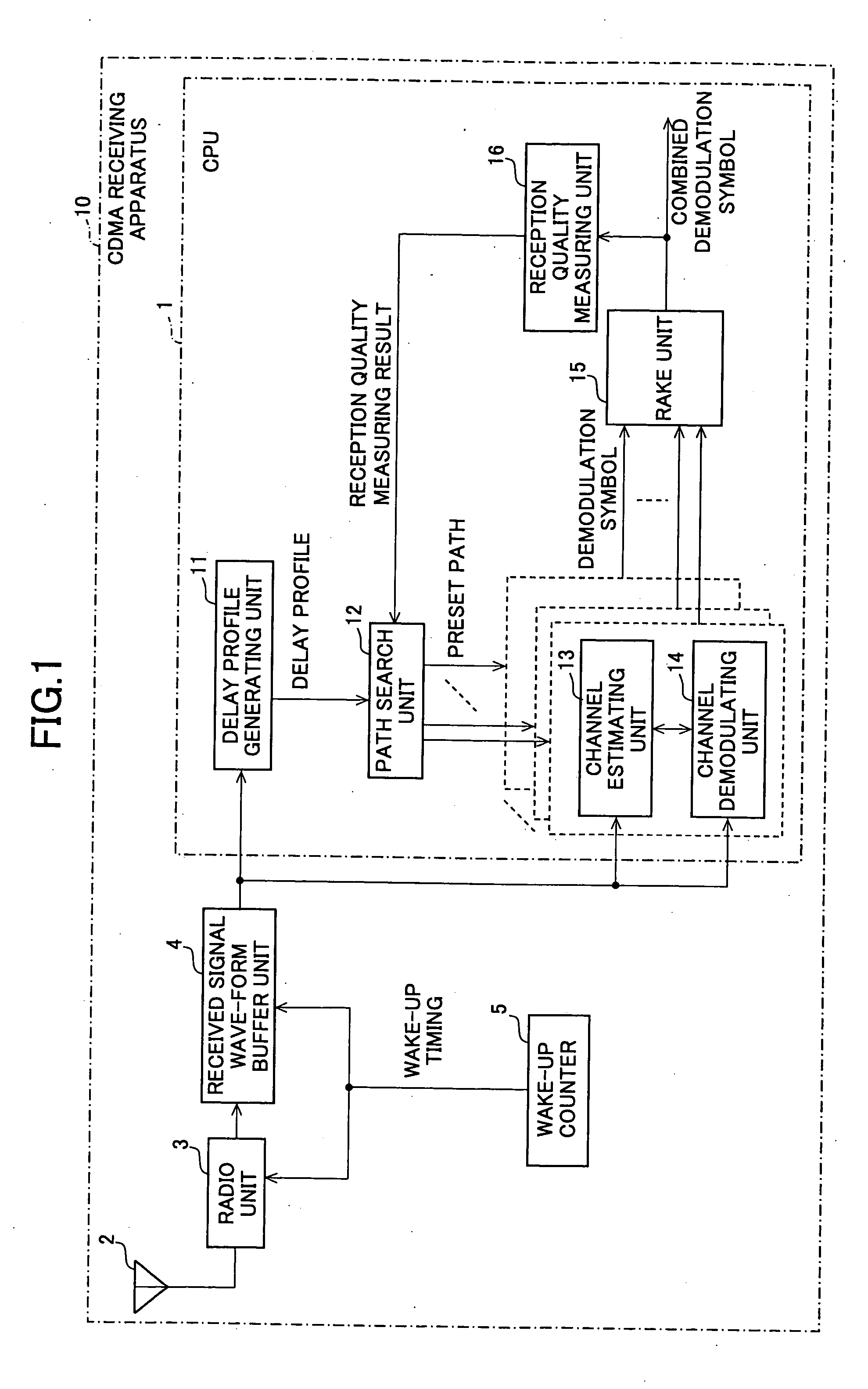
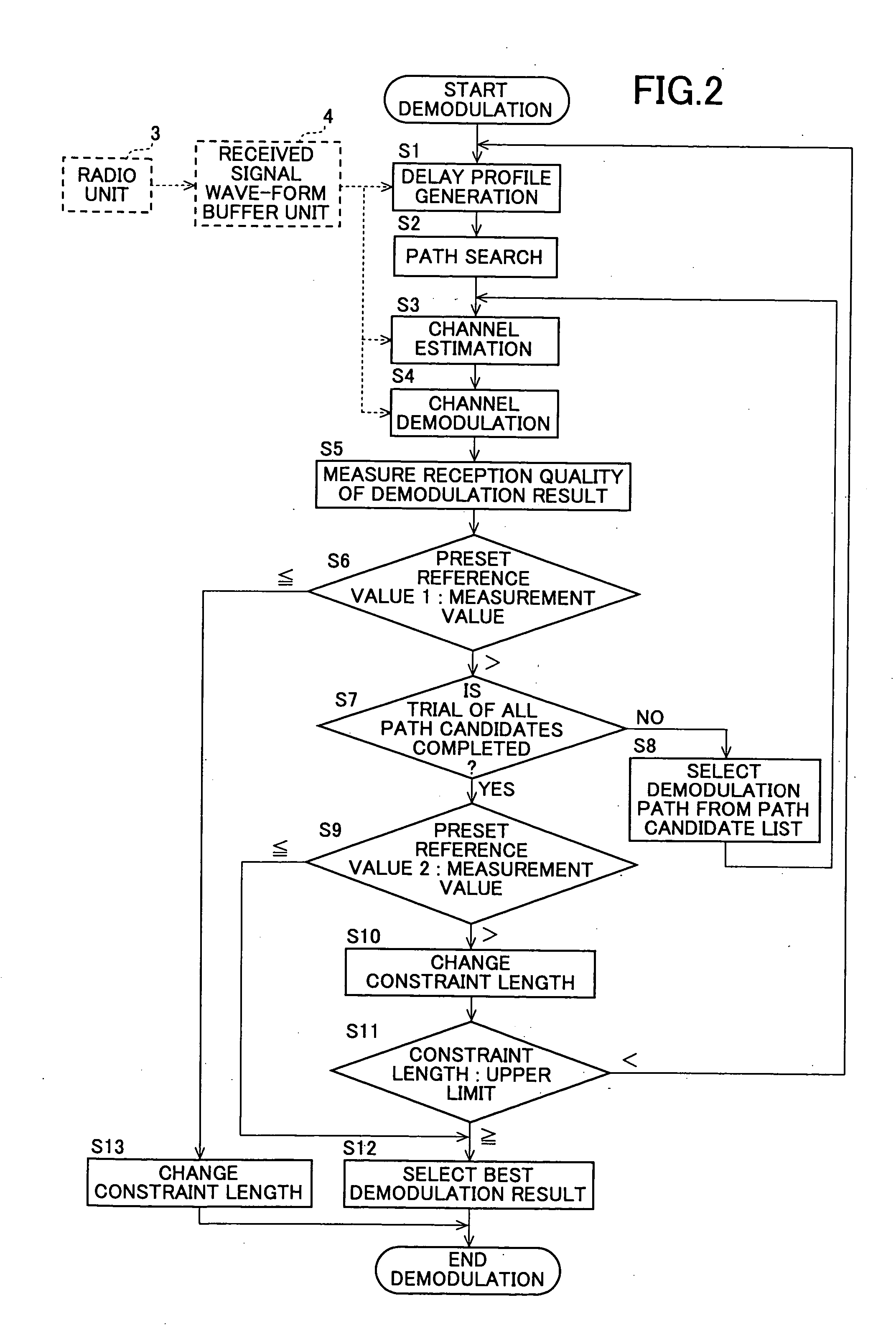
[0052] The CDMA receiving apparatus, CDMA receiving method, CDMA receiving program and program recording medium of the present invention comprises a received signal wave-form buffer unit which is capable of recording received signal wave-form data in which the amplitude of the received signal wave-form is digitalized on different recording areas for each unit processing length. A delay profile which represents the signal power distribution relative to the delay time on a path is generated by multiplying said received signal wave-form data by a demodulation code and determining a sum for a time interval which is given as a desired constraint length. The timing position at which the signal power peaks is determined as a path candidate used for signal demodulation based upon the generated delay profile. A plurality of demodulation paths which is as many as the number of predetermined demodulation paths are selected from said path candidates. After each demodulation symbol of demodulati...


PUM


Abstract

In a CDMA receiving apparatus, a delay profile using a desired constraint length is generated by a delay profile generating unit from received signal wave-form data recorded on a received signal wave-form buffer unit. Several demodulation paths are selected at peak position of the delay profile by the path search unit. Demodulation symbols which are generated from received signal wave-form data of each demodulation path by the channel demodulating unit are brought into in-phase by an adjustment angle which is obtained by the channel estimating unit. If the reception quality which is measured by the reception quality measuring unit is lower than a predetermined value for a combined demodulation symbol which is combined by a RAKE unit, the combination of said selected demodulation paths or the constraint length is changed to repeat the demodulation operation of the same received signal wave-form data.

Description

BACKGROUND OF INVENTION [0001] The present invention relates to a CDMA receiving apparatus, CDMA receiving method, CDMA receiving program and program recording medium and in particular to a mobile CDMA receiving apparatus, CDMA receiving method, CDMA receiving program and a program recording medium in a cellular system using a CDMA scheme. [0002] If a CDMA (code division multiple access) scheme is used for a mobile communication such as cellular phone, the same frequency band can be used on a plurality of channels at the same time. On the transmitter side, a signal to be transmitted is multiplied by a diffusion code which is different for each channel and is then transmitted as so-called diffused signal. Since a code series, the rate of which is tens or hundreds times as high as that of transmission symbol data as the diffusion code, symbol data is diffused in a wider frequency band and transmission is conducted. On the other hand, on the side of CDMA receiving apparatus, transmitte...

Claims


Application Information

Patent Timeline
Patent Type & Authority Applications(United States)
IPC IPC(8): H04B1/707H04B1/10H04B1/7117H04B1/712H04B7/26H04L7/00
CPCH04B1/7117H04B1/7113
Inventor SUGAHARA, SHIRO
Owner SHARP KK
Why Eureka
Try Eureka