Microfluidic pump driven by thermoacoustic effect

Inactive Publication Date: 2005-03-03
IND TECH RES INST
View PDF3 Cites 2 Cited by
  • Summary
  • Abstract
  • Description
  • Claims
  • Application Information

AI Technical Summary

Benefits of technology

[0006] The main objective of the present invention is to provide a microfluidic pump driven by thermoacoustic effect, comprising thermoacoustic device, fluid-storing tank, and microchannels, wherein the thermoacoustic device is the source generating acoustic wave of high frequency and high acoustic energy, and the microchannels are arranged upon the tank body of the fluid-storing tank that is combined with the thermoacoustic device. By the design of the aforementioned structure, the present invention may apply the acoustic wave, with high frequency and high energy, generated by the thermoacoustic device to drive the working fluid contained in the fluid-storing tank by indirectly contacting manner, such that the driven microfluid may be discharged through the microchannels. Since the microfluid of the present invention is driven indirectly so, compared with the directly driving manners of prior arts that apply electrodes or heat to the working fluids with direct contact, the invention not only may be extensively applied to non-conductive fluids, but also may greatly increase the fields and kinds of applicable fluid.
[0007] Another objective of the invention is to provide a microfluidic pump driven by thermoacoustic effect, wherein, by changing the structures and arrangement positions of the fluid-storing tank and microchannels thereon, it is possible to generate different flow patterns, such as: micro jet, micro droplet, and microfluidic mixing, etc.

Problems solved by technology

Therefore, there are many limitations unavoidably imposed upon the kinds of fluids that can be used.
For example, the microfluid driving device driven by electrodes is only suitable to be used in conductive fluids, but applying electrode in the bimedical detection process may damage the fluid itself that will have affect on the accuracy of the detection.
In addition, since the thermal bubble-based micropump directly heats and vaporizes the ink itself, the ink used must have stable thermal property, low conductivity, and low chemical activity, which are the reasons why the price of the ink used in ink-jet machine is so high.

Method used


Image

  • Microfluidic pump driven by thermoacoustic effect
  • Microfluidic pump driven by thermoacoustic effect
  • Microfluidic pump driven by thermoacoustic effect

Examples


Embodiment Construction

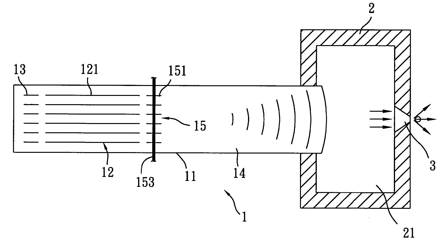
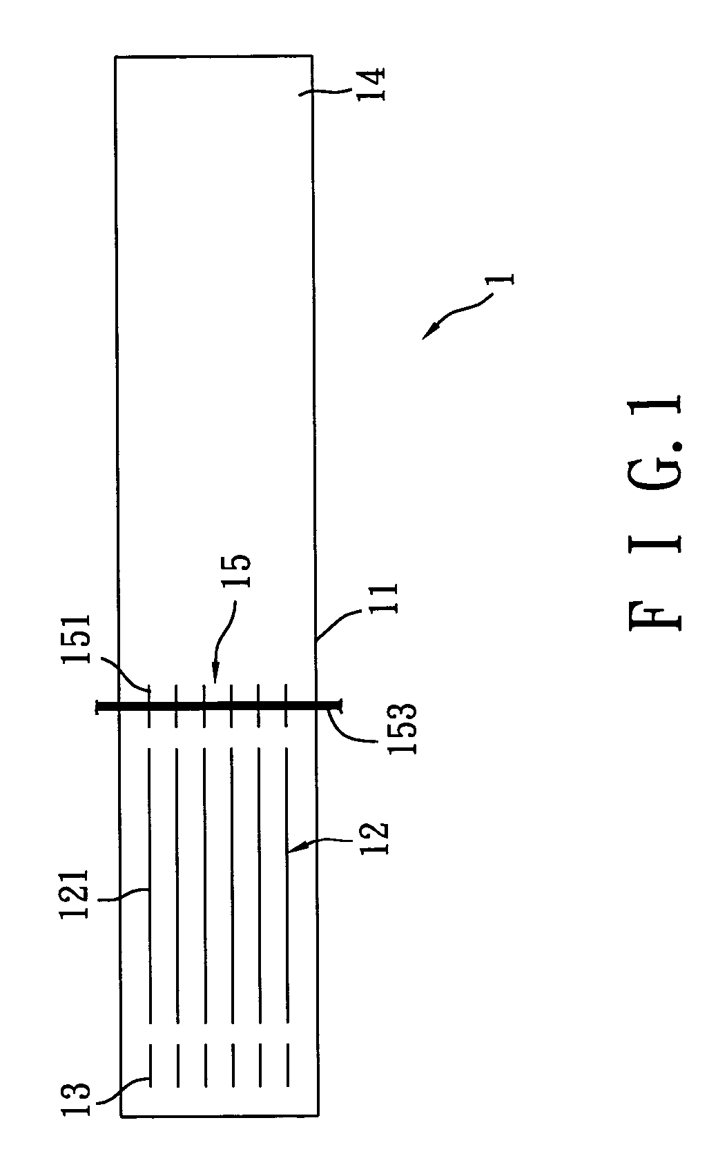
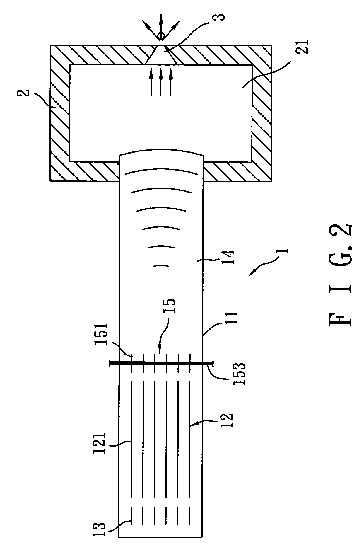
[0014] First, as shown in FIG. 1 and FIG. 2, which are a schematic diagram showing a thermoacoustic device and a diagram showing the first preferred embodiment of the present invention. The microfluidic pump driven by thermoacoustic effect disclosed in the present invention comprises a thermoacoustic device 1, a fluid-storing tank 2, and microchannels 3. Wherein, the thermoacoustic device 1 is the source generating acoustic wave of high frequency and high acoustic energy. The microchannels 3 are arranged at the tank body of the fluid-storing tank 2. The fluid-storing tank 2 is combined with the thermoacoustic device 1. By the design of the aforementioned structure, the present invention may apply the acoustic wave of high frequency and high energy generated by the thermoacoustic device 1 to drive the working fluid 21 stored in the fluid-storing tank 2, such that the driven microfluid can be emitted through the microchannels 3. In the present invention, the working fluid 21 stored in...


PUM


Abstract

A microfluidic pump driven by thermoacoustic effect is mainly composed of a thermoacoustic device, a fluid-storing tank, and at least one microchannel, etc., wherein the thermoacoustic device may convert thermal energy into acoustic energy. Pressure fluctuation and velocity fluctuation with high frequency are generated by the acoustic wave. According to the high amplitude pressure fluctuation, the microfluid with high moving velocity emitted through microchannels. Since there is no movable part arranged in the thermo-acoustic generator. In the meantime, it indirectly drives the working fluid located in the fluid-storing tank by the manner of indirect contact. So the present invention may be applied in the non-conductive fluid so as to greatly extend its field of application. Moreover, the characteristics of the fluid won't be influenced by the heating process as well. The present invention is indeed a microfluid-driving device that has inventiveness and high application value.

Description

FIELD OF THE INVENTION [0001] The invention relates to a microfluidic pump driven by thermoacoustic effect, more particularly, to a microfluidic pump driven by thermoacoustic effect that uses the thermoacoustic effect for converting thermal energy into acoustic energy to generate high-amplitude pressure fluctuation and velocity fluctuation for driving microfluid. BACKGROUND OF THE INVENTION [0002] Following the rapid development of modern technology, microfluidic pump is widely applied in all kinds of hi-tech field, such as biomedical detection and inkjet printing. The so-called “microfluid driving system” may be further classified as the follows according to its function: micro jet, micro droplet, and microfluidic mixing. Currently, there are many methods by which fluid actuation through microchannels can be achieved, including the direct usage of micropump or thermal bubble pumping, both of which drive microfluid by direct contact. The former, i.e. micropump, is widely applied in ...

Claims


Application Information

Patent Timeline
IPC IPC(8): B01L3/02F04B17/00F04B19/00F04F7/00
CPCB01L3/0268B01L2400/0436F04F7/00F04B19/006F04B17/00
Inventor CHOU, YA-WENHOO, MEEN-DAULIN, CHIH-CHIEH
Owner IND TECH RES INST
Why Eureka
Try Eureka