Wireless communication system with a supplemental communication sub-system

Inactive Publication Date: 2005-03-03
LUCENT TECH INC
View PDF23 Cites 0 Cited by
  • Summary
  • Abstract
  • Description
  • Claims
  • Application Information

AI Technical Summary

Benefits of technology

Problems in the prior art are addressed, in accordance with the principles of the present invention, by a wireless communication system having primary and supplemental communication sub-systems. The primary communication sub-system includes a plurality of base stations and a mobile services switching center (MSC) of the prior art. The supplemental communication sub-system includes one or more supplemental transceiver units (STUs) controlled by a supplemental switching center (SSC) having access to a public switched telephone network (PSTN). Each STU has a primary function and, in addition, is adapted to support (i) a wireless communication link with at least one mobile station and (ii) a wire-line communication link with the SSC. In one embodiment, an STU of the invention has a conventional TV receiver and a TV screen whose primary function is to receive and display television programs supplied over a cable network. In addition, the STU has an RF transceiver designed to support a wireless communication link with N mobile stations and an interface designed to support, over the same cable network used for transmitting the television signals, a cable communication link with a service distribution node of the cable service provider, which node is configured to perform the functions of an SSC. Advantageously, a wireless communication system of the invention may have a smaller area affected by blind spots compared to that in prior-art systems. In addition, the supplemental communication sub-system provides additional communication capacity, which may be utilized to improve performance, for example, when call volume processed by the primary communication sub-system becomes relatively high.

Problems solved by technology

Actual shapes and sizes of cells in the communication structure are complex functions of the transmitted RF power, the terrain, the man-made environment, and the required quality of communication and user capacity.
For example, blind spots are often present in building interiors due to the substantial RF power attenuation by metal parts in the building structure.

Method used


Image

  • Wireless communication system with a supplemental communication sub-system
  • Wireless communication system with a supplemental communication sub-system
  • Wireless communication system with a supplemental communication sub-system

Examples


Embodiment Construction

Reference herein to “one embodiment” or “an embodiment” means that a particular feature, structure, or characteristic described in connection with the embodiment can be included in at least one embodiment of the invention. The appearances of the phrase “in one embodiment” in various places in the specification are not necessarily all referring to the same embodiment, nor are separate or alternative embodiments mutually exclusive of other embodiments.

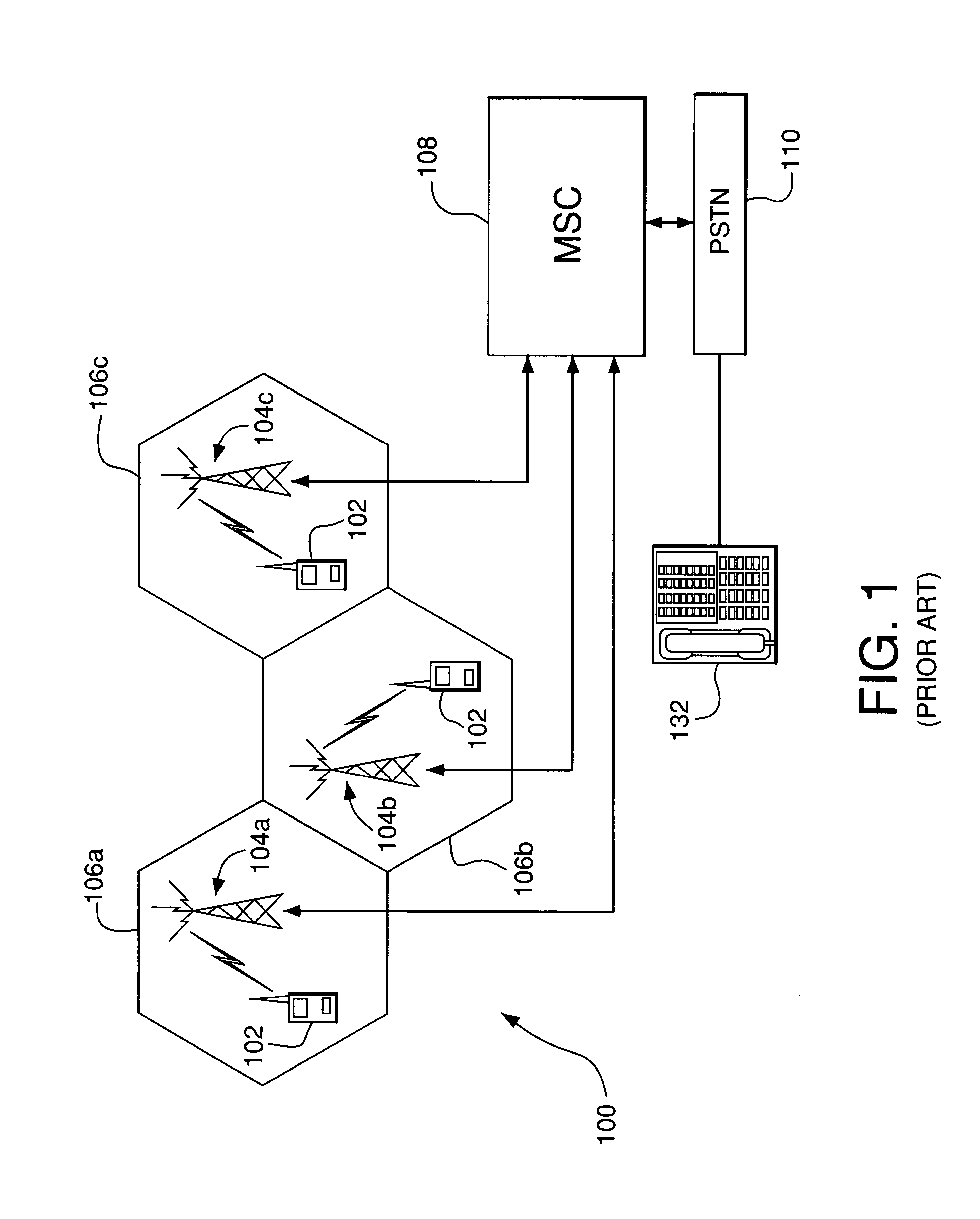
FIG. 1 shows a diagram of a prior-art wireless communication system 100. More specifically, system 100 includes a plurality of base stations 104 communicating with one or more mobile stations 102. Each base station (BS) 104 serves a cell 106 illustratively indicated in FIG. 1 by a hexagon. BS 104 is designed to provide (i) wireless links with mobile stations located within cell 106 and (ii) a wire-line link with a mobile services switching center (MSC) 108. MSC 108 is designed to control the operation of base stations 104 connected to ...


PUM


Abstract

A wireless communication system having primary and supplemental communication sub-systems. The primary communication sub-system includes a plurality of base stations and a mobile services switching center (MSC) of the prior art. The supplemental communication sub-system includes one or more supplemental transceiver units (STUs) controlled by a supplemental switching center (SSC) having access to a public switched telephone network. Each STU has a primary function and, in addition, is adapted to support (i) a wireless communication link with at least one mobile station and (ii) a wire-line communication link with the SSC. In one embodiment, an STU of the invention has a conventional TV receiver and a TV screen whose primary function is to receive and display television programs supplied over a cable network. In addition, the STU has an RF transceiver designed to support a wireless communication link with N mobile stations and an interface designed to support, over the same cable network used for transmitting the television signals, a cable communication link with a service distribution node of the cable service provider, which node is configured to perform the functions of an SSC.

Description

BACKGROUND OF THE INVENTION 1. Field of the Invention The present invention relates to wireless communication systems. 2. Description of the Related Art Wireless communication systems are extensively used to provide communication services to a wide array of users. A typical wireless communication system includes a plurality of base stations (BSs), each BS configured to communicate with mobile stations located in proximity to that BS. Base stations are appropriately spaced to create a communication structure, in which each BS covers a certain geographical area (cell). A typical BS has an antenna system coupled to a radio frequency (RF) transceiver to provide wireless links with mobile stations. In addition, each BS has an interface system to provide a wire-line link with a mobile services switching center (MSC). The MSC controls the operation of base stations in the assigned area and serves as a gateway between those base stations and the public switched telephone network (PSTN)....

Claims


Application Information

Patent Timeline
IPC IPC(8): H04W16/26H04W88/16H04W92/14
CPCH04W16/26H04W92/14H04W88/16
Inventor HAUEIS, MARTIN
Owner LUCENT TECH INC
Why Eureka
Try Eureka