Uncaging device

a technology of uncaging devices and caged compounds, which is applied in the field of uncaging devices, can solve the problems of inability to uncage samples in multi-well plates, test tubes, or other common laboratory formats, and achieve the effect of reducing the optical power density

Active Publication Date: 2005-03-10
AFFYMETRIX INC
View PDF9 Cites 17 Cited by
  • Summary
  • Abstract
  • Description
  • Claims
  • Application Information

AI Technical Summary

Benefits of technology

[0008] Another aspect of the invention provides masked multiwell plates. Thus, one general class of embodiments provides a masked multiwell plate that comprises a multiwell plate and a mask. The mask alters optical power density of uncaging light impinging on at least a first portion of the multiwell plate (e.g., on at least one well or portion of a well). In some embodiments, the mask inhibits or prevents the uncaging light from impinging on at least the first portion of the multiwell plate and permits the uncaging light to impinge on at least a second portion of the multiwell plate. In other embodiments, the mask decreases the optical power density of the uncaging light impinging on the first portion of the multiwell plate, but does not completely block transmission of the uncaging light.

Problems solved by technology

However, the utility of such photolabile caged compounds (and other photoactivatable compounds) has been limited by lack of a convenient technology for uncaging the compounds reproducibly, uniformly, and safely, across various formats.
However, these devices cannot uncage samples in multiwell plate, test tube, or other common laboratory formats.

Method used


Image

  • Uncaging device
  • Uncaging device
  • Uncaging device

Examples


examples

[0080] It is understood that the examples and embodiments described herein are for illustrative purposes only and that various modifications or changes in light thereof will be suggested to persons skilled in the art and are to be included within the spirit and purview of this application and scope of the appended claims. Accordingly, the following examples are offered to illustrate, but not to limit, the claimed invention.

[0081] Evaluation of Optical Power Density Uniformity

[0082] To determine whether commercially available UV exposure systems can be adapted for use as portions of example uncaging devices (e.g., devices producing uncaging light in the UV wavelength range), uniformity of the light produced by five such commercial devices was evaluated. UV exposure systems tested were Model 66-5 from AB Manufacturing Inc. (ABM, www.abmfg.com), Model LS30 / 7 from Optical Associates Inc. (OAI, www.oainet.com), Model 82530-1000 from Spectra-Physics' Oriel Division (www.oriel.com), Mode...

example instrument

Description

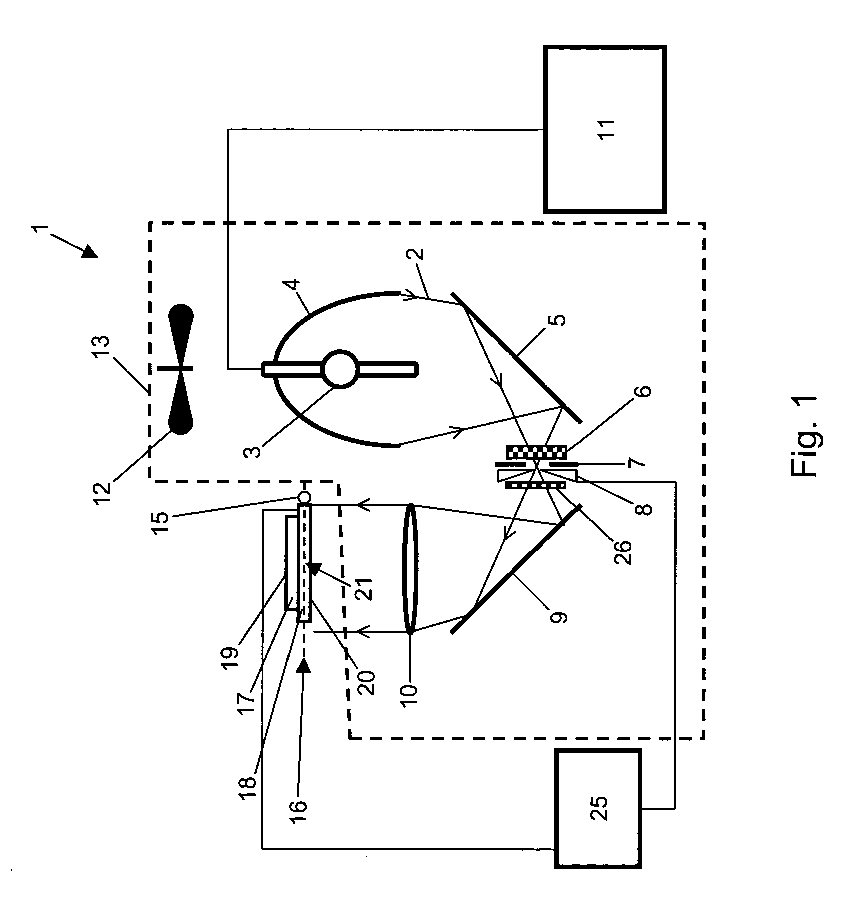
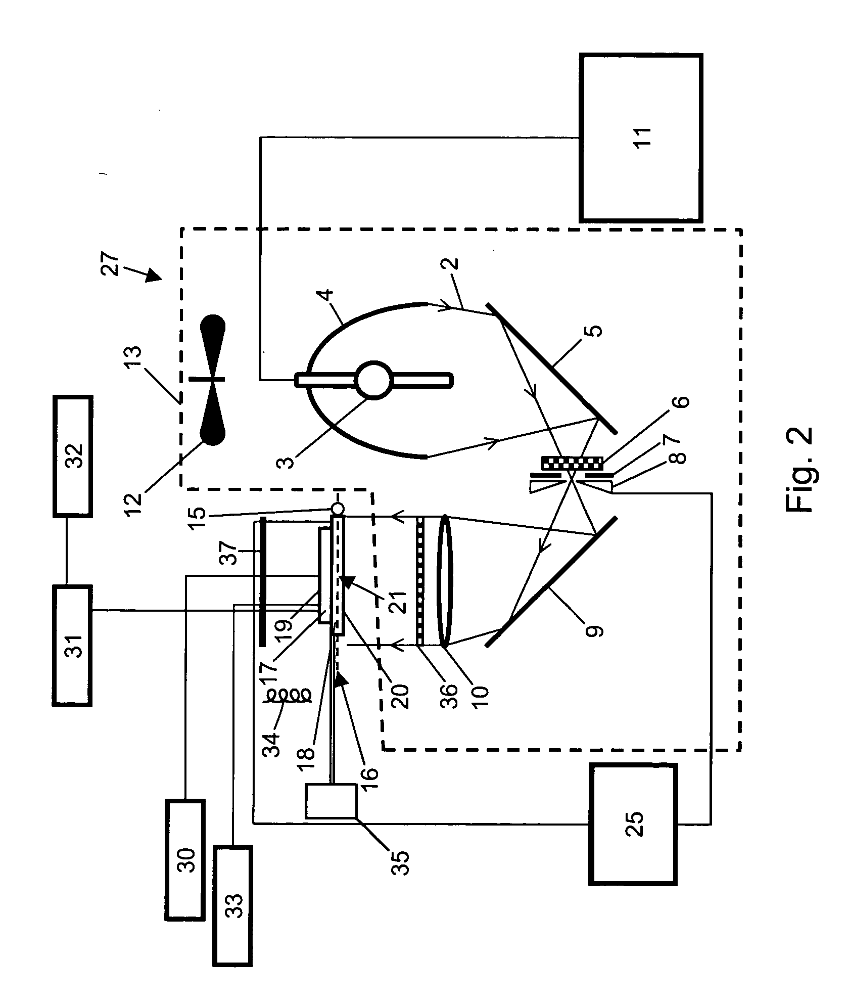
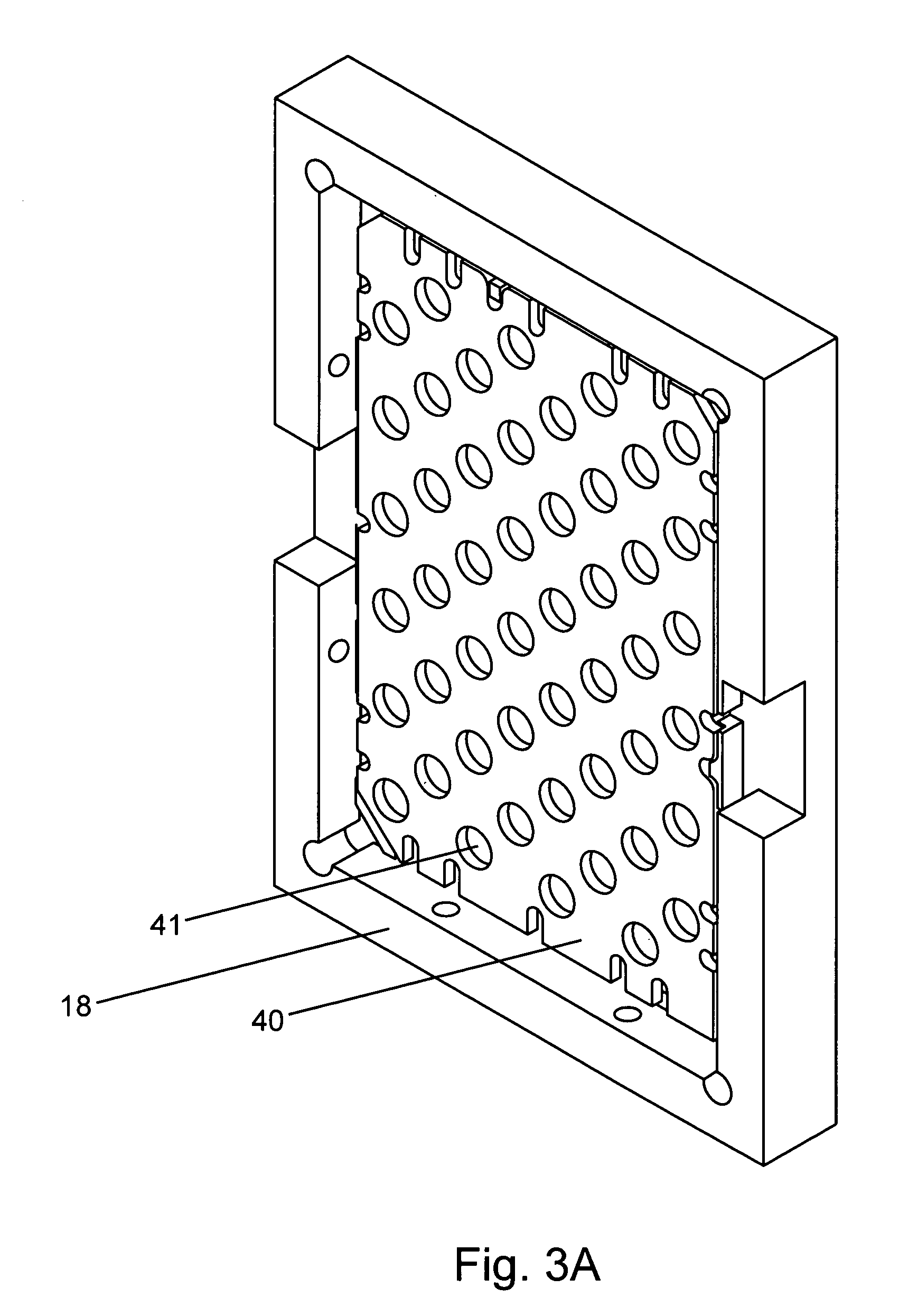
[0093] The instrument typically has illumination sources for uncaging, stimulation and / or detection, a mechanism to control the illumination power and / or energy density, and an optical set-up to guide the light from illumination source to sample. A calibration light meter can be used to ensure reproducible exposure and automated power and location adjustments. Mechanical design can be used to manipulate samples and / or optics in an x, y or z direction depending on specific application and assay format. A liquid handling mechanism is preferably integrated into the reaction holder.

[0094] The illumination source(s) can be, e.g., continuous or pulse lasers, flash lamps (e.g., Xenon or Mercury), continuous lamps and others. The light can be guided to the sample with one or more optical mirror, lens, fiber optic bundle, or the like. Illumination dimension (focus or broad beam) can be controlled using lenses or mirrors, for example. Uniform illumination can be achieved, e.g., by...


PUM

PropertyMeasurementUnit
wavelengthaaaaaaaaaa

Abstract

Uncaging devices that can be used to uncage photoactivatable caged components are provided. Consistent, uniform and / or high throughput processing of reactions and assays that include caged components is provided. Masked multiwell plates that can be used for uncaging photoactivatable caged components are provided. Methods and apparatus for initiating assays involving caged components are provided.

Description

CROSS REFERENCE TO RELATED APPLICATIONS [0001] This application is a non-provisional utility patent application claiming priority to and benefit of the following prior provisional patent applications: U.S. Ser. No. 60 / 427,664, filed Nov. 18, 2002, entitled “Photo Activated Sensors, Regulators and Compounds” by Nguyen and McMaster, U.S. Ser. No. 60 / 436,855, filed Dec. 26, 2002, entitled “Caged Sensors, Regulators and Compounds and Uses Thereof” by Nguyen and McMaster, U.S. Ser. No. 60 / 439,917, filed Jan. 13, 2003, entitled “Caged Sensors, Regulators and Compounds and Uses Thereof” by Nguyen and McMaster, U.S. Ser. No. 60 / 451,177, filed Feb. 27, 2003, entitled “Caged Sensors, Regulators and Compounds and Uses Thereof” by Nguyen et al., U.S. Ser. No. 60 / 456,870, filed Mar. 21, 2003, entitled “Caged Sensors, Regulators and Compounds and Uses Thereof” by Nguyen et al., and U.S. Ser. No. 60 / 501,599, filed Sep. 9, 2003, entitled “Caged Sensors, Regulators and Compounds and Uses Thereof” by...

Claims


Application Information

Patent Timeline
Patent Type & Authority Applications(United States)
IPC IPC(8): A61K48/00C07H21/02C12Q1/68G01J1/00G01J1/42G01J3/30G01NH01J40/14
CPCG01N21/6452
Inventor WITNEY, FRANKMCMASTER, GARYNGUYEN, QUANCHEN, STEVE
Owner AFFYMETRIX INC
Why Eureka
Try Eureka