
Non-linear Raman spectroscopy apparatus, non-linear system, and non-linear raman spectroscopy method

a raman spectroscopy and nonlinear technology, applied in the field of nonlinear raman spectroscopy apparatus, nonlinear raman spectroscopy system and nonlinear raman spectroscopy method, can solve the problems of reducing the optical power density per unit wavelength, limiting the maximum incident power, and large optical damage, etc., to achieve the quality of input laser beams, improve the nonlinear optical effect, and improve the effect of nonlinear optical

Inactive Publication Date: 2014-10-28
SONY CORP
View PDF6 Cites 1 Cited by
  • Summary
  • Abstract
  • Description
  • Claims
  • Application Information

AI Technical Summary

Benefits of technology

The patent text discusses the use of certain methods in spectroscopy, such as PCF and HNLF. These methods provide a wider range of light wavelengths that can be analyzed. However, this wider range can result in weaker optical power, meaning the amount of light per unit wavelength is reduced. The technical effect of this patent is to address this issue and improve the quality of optical power in spectroscopy methods that use PCF or HNLF.

Problems solved by technology

However, in the non-linear Raman spectroscopy in the past described above, particularly multiplex CARS spectroscopy, broadband white light is generated with a PCF, a highly non-linear fiber (HNLF), or the like, thereby causing a large optical damage particularly near an incident end face to limit a maximum incident power.
In CARS spectroscopy, however, the excess wideness results in decrease of optical power density per unit wavelength.
Also, the PCF has a problem such that a special end-face processing is to be performed.
Moreover, a beam profile of supercontinuum light (beam) generated from a PCF is generally not that of an ideal Gaussian beam.
Laser light having this beam profile is not preferable because this may cause degradation of an image obtained by microspectroscopy or microspectroscopic imaging.

Method used


Image

  • Non-linear Raman spectroscopy apparatus, non-linear system, and non-linear raman spectroscopy method
  • Non-linear Raman spectroscopy apparatus, non-linear system, and non-linear raman spectroscopy method
  • Non-linear Raman spectroscopy apparatus, non-linear system, and non-linear raman spectroscopy method

Examples


embodiment

1. Embodiment

[0046](Example of an apparatus using a single-mode fiber for generation of a Stokes beam)

2. Another Embodiment[0047](Example of an apparatus in which an optical fiber is placed on an optical path of a pump-cum-probe beam)

3. Still Another Embodiment[0048](Example of a system including a computing unit normalizing a measured spectrum) 1. Embodiment

Entire Structure of the Apparatus

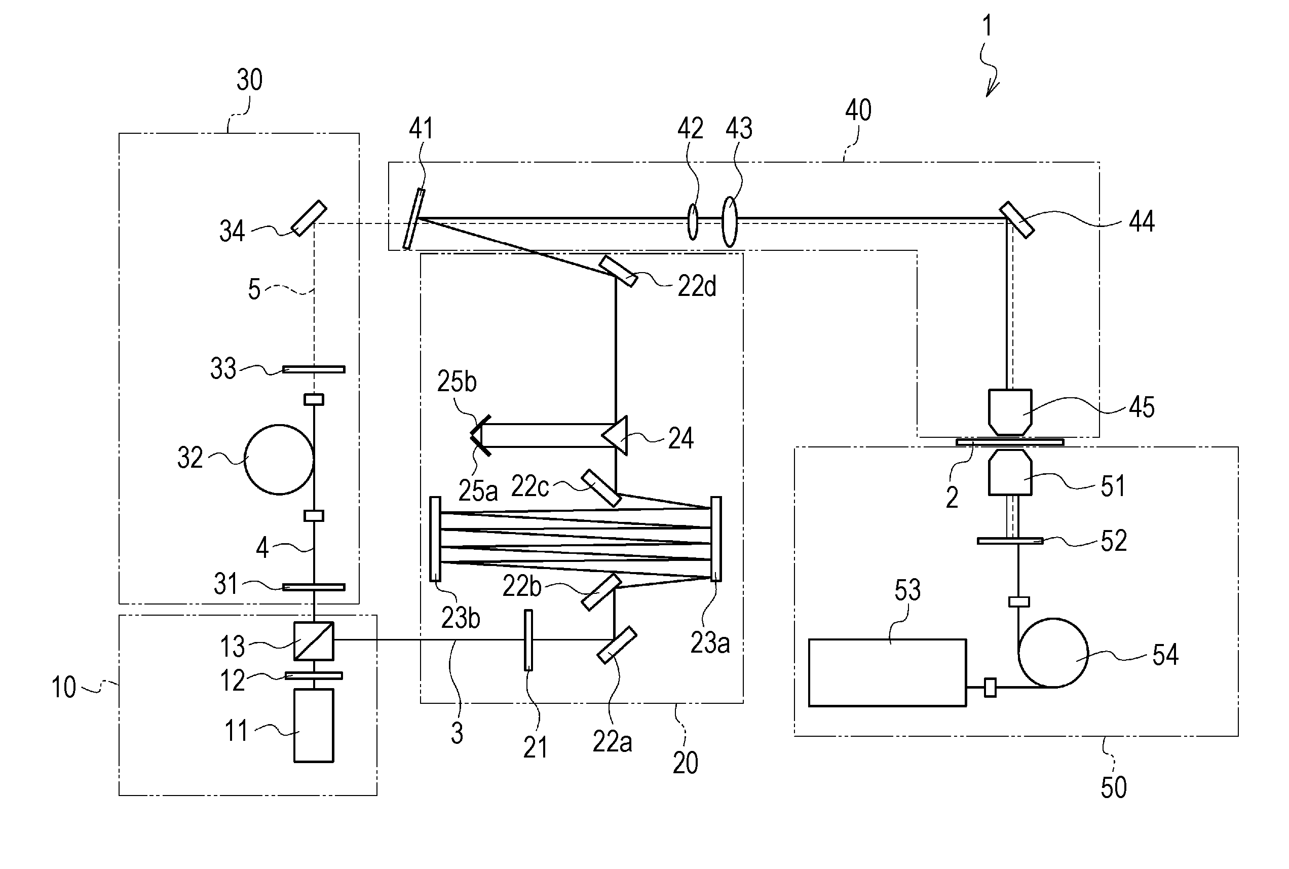
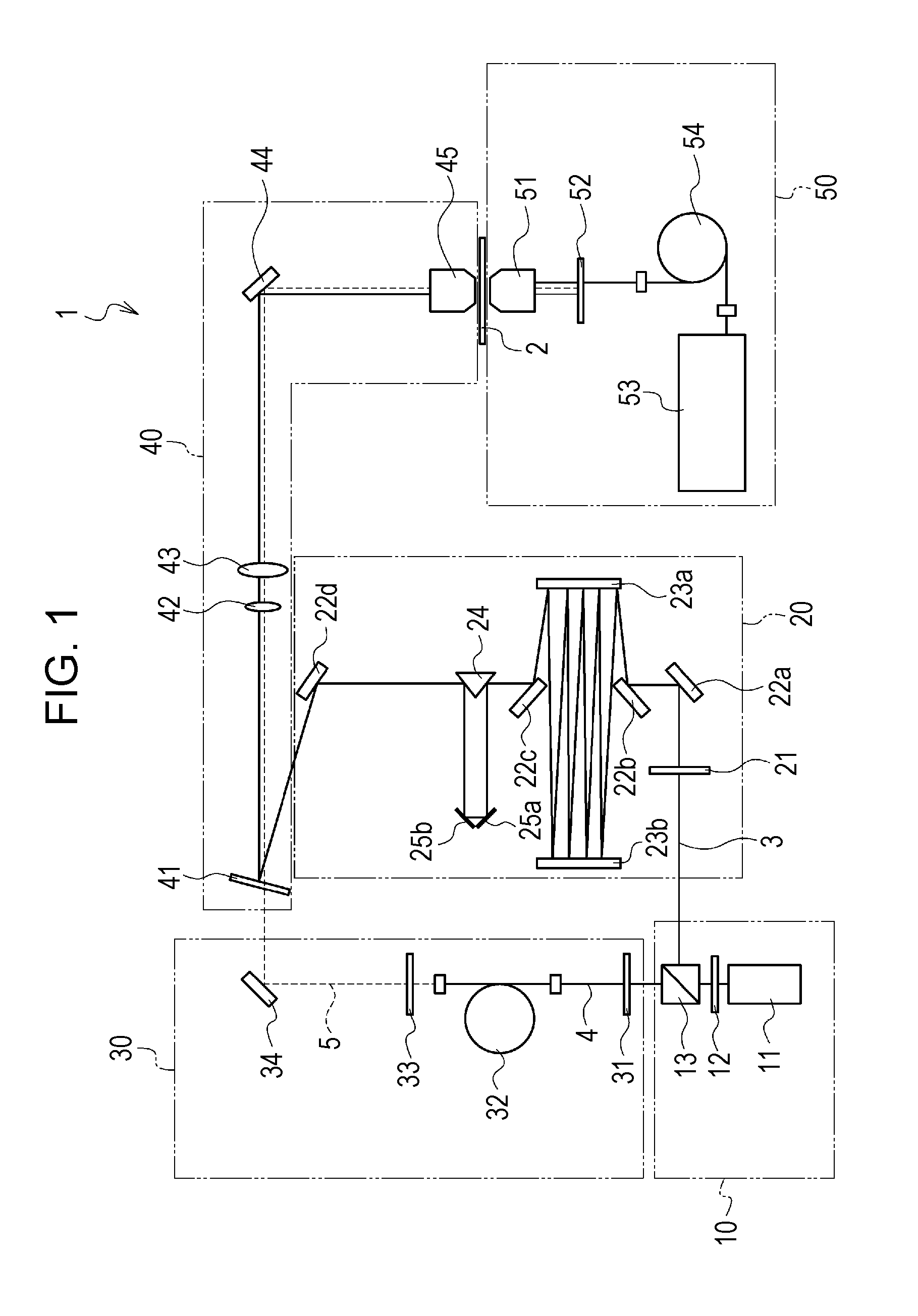
[0049]First, a non-linear Raman spectroscopy apparatus according to an embodiment of the present disclosure is described. FIG. 1 is a schematic diagram of the structure of a non-linear Raman spectroscopy apparatus of the present embodiment. A non-linear Raman spectroscopy apparatus 1 of the present embodiment is a CARS spectroscopy apparatus and, as shown in FIG. 1, is provided with a light source unit 10, a pump-cum-probe-beam generating unit 20, a Stokes-beam generating unit 30, a beam radiating unit 40, and a measuring unit 50.

Light Source Unit 10

[0050]The light source unit 10 includes at leas...


PUM

PropertyMeasurementUnit
wavelengthaaaaaaaaaa
lengthaaaaaaaaaa
core diameteraaaaaaaaaa

Abstract

A non-linear Raman spectroscopy apparatus includes a light source unit emitting a pulse beam having a pulse width of 0.2 ns to 10 ns, a pulse peak power of 50 W to 5000 W, and a wavelength of 500 nm to 1200 nm, and a single-mode fiber through which continuous white light is generated from the pulse beam. A test sample to be measured is radiated with a pump-cum-probe beam formed of the pulse beam and a Stokes beam formed of the continuous white light to obtain a Raman spectrum.

Description

CROSS REFERENCES TO RELATED APPLICATIONS[0001]The present application claims priority to Japanese Priority Patent Application JP 2011-079473 filed in the Japan Patent Office on Mar. 31, 2011, the entire content of which is hereby incorporated by reference.BACKGROUND[0002]The present disclosure relates to a non-linear Raman spectroscopy apparatus, and a non-linear Raman spectroscopy system and non-linear Raman spectroscopy method that use this apparatus. In more detail, the present disclosure relates to an apparatus, system, and method for multiplex coherent anti-Stokes Raman spectroscopy using a broadband light source as a Stokes beam.[0003]Laser Raman spectroscopy is an analysis method of radiating a test sample with laser light having a single wavelength as a pump beam and obtaining spectrums of light scattered from the test sample. A shift amount of the wave number of a Stokes beam or an anti-Stokes beam, which is the scattered light mentioned above, with respect to the wave numb...

Claims


Application Information

Patent Timeline
Patent Type & Authority Patents(United States)
IPC IPC(8): G01N21/65G01J3/44
CPCG01N21/65
Inventor TAMADA, SAKUYA
Owner SONY CORP
Learn More