A cone-rod laser amplifier

A laser amplifier and seed technology, applied in lasers, laser parts, laser parts, etc., can solve the problems of unable to provide sufficient gain, unable to fully utilize the round rod gain medium, low repetition frequency output, etc., to reduce the optical power density , Simple structure, reducing the effect of components

Active Publication Date: 2021-08-03
四川光天下激光科技有限公司
View PDF9 Cites 0 Cited by
  • Summary
  • Abstract
  • Description
  • Claims
  • Application Information

AI Technical Summary

Problems solved by technology

[0004] The invention proposes a cone-rod laser amplifier to solve the problem that the energy storage of the existing round rod gain medium cannot be fully utilized or the energy storage cannot provide sufficient gain, especially suitable for small laser

Method used


Image

  • A cone-rod laser amplifier
  • A cone-rod laser amplifier
  • A cone-rod laser amplifier

Examples


Embodiment 1

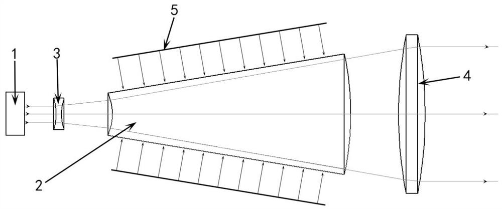
[0032] This embodiment provides a cone-rod laser amplifier, including a pumping source 5, a seed source 1, a diverging lens 3, a cone-rod gain medium 2 and a collimating lens 4 coaxially arranged in sequence, the seed source 1 and the pumping source 5 emit seed light and pump light respectively, the structure is as follows figure 1 shown.

[0033] The diverging lens 3 will be 3mm*3mm (or 3mm) parallel incident seed light diverges with a divergence angle of 5°.

[0034] The cone-rod gain medium 2 uses Nd:YAG crystal, Nd 3+ The doping concentration is 0.8%, and the length is 85 mm; the incident end surface of the cone-rod gain medium 2 is the spherical cap of the spherical cone A, the spherical radius of the spherical cone A is 45 mm, the center of the sphere coincides with the focal point of the diverging lens, and the incident end surface The radius of the bottom is 4 mm, and the height is 0.18 mm; the exit end surface is the spherical cap of the spherical cone B, the sph...

Embodiment 2

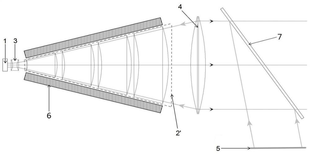
[0041] This embodiment provides a multi-stage cone-rod laser amplifier, including a pump source 5, a heat sink 6, a dichroic mirror 7, and a seed source 1, a diverging lens 3, and a cone-rod gain medium group 2' coaxially arranged in sequence. And collimating lens 4, seed source 1 and pump source 5 emit seed light and pump light respectively, the structure is as follows figure 2 shown.

[0042] The diverging lens 3 will 3 mm parallel incident seed light diverges with a spread angle of 5°.

[0043] The cone-rod gain medium group 2' is composed of a multi-stage cone-rod gain medium, the overall profile is in the shape of a spherical cone, and Nd:YAG crystal is used, wherein Nd 3+ The doping concentration is 0.8%; the incident end face and the exit end face of the cone-rod gain medium at all levels are spherical cone spherical caps, and the centers of the spheres coincide with the focus of the diverging lens 3, and the center angles are equal. The length of the medium is 20...

Embodiment 3

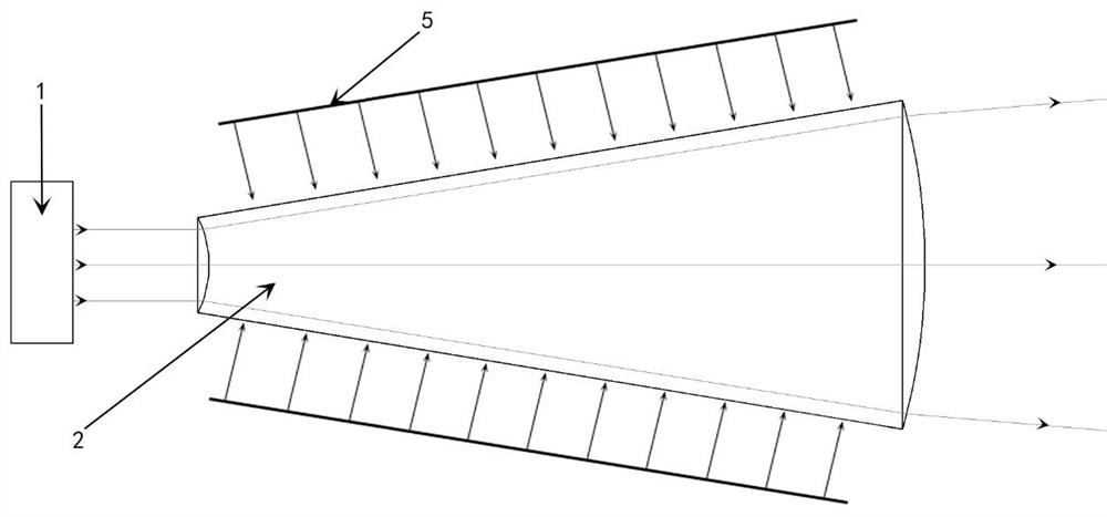
[0050] This embodiment provides an improved cone-rod laser amplifier, including a pumping source 5, a seed source 1 and a cone-rod gain medium 2 coaxially arranged, and the seed source 1 and the pumping source 5 send out seed light and pumping light respectively. light, structured as image 3 shown.

[0051] The cone-rod gain medium 2 is Nd:YAG crystal, Nd 3+ The doping concentration is 0.8%, and the refractive index n=1.82; the cone-rod gain medium 2 is an axirotationally symmetrical figure, its incident end surface is the spherical cap of spherical cone A, its outgoing end surface is the spherical cap of spherical cone B, and its side is a frustum of a cone side; wherein, the spherical cone A and the spherical cone B are coaxial, and are located on the rotational symmetry axis of the incident or outgoing end surface close to the seed source; the spherical radius of the spherical cone A is 15.53 mm, and the bottom of the incident end surface is The diameter is 4mm, larger t...


PUM

PropertyMeasurementUnit
refractive indexaaaaaaaaaa

Abstract

A cone-rod laser amplifier provided by the present invention belongs to the field of solid-state lasers, and includes a pump source, a seed source, a diverging lens, a cone-rod gain medium and a collimating lens arranged coaxially in sequence, the incident end face of the cone-rod gain medium and The exit end surface is coaxial and the spherical conical cap of the spherical cone is located at the focal point of the diverging lens, which satisfies:; The present invention also proposes a cone-rod gain medium group composed of multi-stage cone-rod gain media with a spherical conical profile , and the improved cone-rod laser amplifier with the cone-rod gain medium itself having the function of a diverging lens, so that the maximum efficiency of the seed light energy can be extracted from the energy storage of the reversed particle number in the cone-rod gain medium, so that the cone-rod laser amplifier can work close to saturation state; the cone-rod laser amplifier proposed by the present invention is small in size and simple in structure.

Description

technical field [0001] The invention belongs to the field of solid lasers, in particular to a laser amplifier. Background technique [0002] Solid-state laser amplifiers are an effective way to obtain high-power, high-beam-quality laser output. At present, the shape of the laser gain medium used in solid-state lasers is slab or rod. Among them, the rod-shaped gain medium has the advantages of low price, simple structure, and high-power laser output. It is widely used in industry, scientific research and other fields due to its advantages. [0003] In order to extract more energy from the rod-shaped gain medium, the amplifier often uses a double-pass or multi-pass structure, resulting in a laser amplifier with complex structure, large volume, and difficult debugging. Improving the light-to-light conversion efficiency can increase the gain obtained from the gain medium in a single pass, which can avoid the use of double-pass or multi-pass structures to a certain extent. For s...

Claims


Application Information

Patent Timeline
Patent Type & Authority Patents(China)
IPC IPC(8): H01S3/06H01S3/10H01S3/13H01S3/04H01S3/042
CPCH01S3/0405H01S3/042H01S3/0617H01S3/10007H01S3/1301
Inventor 彭艳红杨毅
Owner 四川光天下激光科技有限公司
Why Eureka
Try Eureka