
A Curved Slab Laser Amplifier

A technology of laser amplifiers and curved panels, which is applied to lasers, laser components, phonon exciters, etc., can solve the problem of not being able to fully utilize the slab medium for energy storage, and achieve a simple structure, small volume, and stable optical power density Effect

Active Publication Date: 2021-08-10
四川光天下激光科技有限公司
View PDF2 Cites 0 Cited by
  • Summary
  • Abstract
  • Description
  • Claims
  • Application Information

AI Technical Summary

Problems solved by technology

[0004] Aiming at the problem that the energy storage of the existing slab medium cannot be fully utilized in the above-mentioned prior art, the present invention proposes a curved slab laser amplifier, which significantly improves the utilization rate of the slab medium

Method used


Image

  • A Curved Slab Laser Amplifier
  • A Curved Slab Laser Amplifier
  • A Curved Slab Laser Amplifier

Examples


Embodiment 1

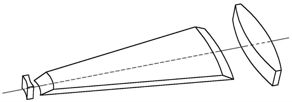
[0030] This embodiment provides a curved slab laser amplifier, including a pump source 4, a heat sink 5, and a seed source 1, a diverging cylindrical lens 3, a curved slab medium 2 and a collimating cylindrical lens 6 coaxially arranged in sequence, Its structure is as figure 1 and image 3 As shown, the pumping light emitted by the pumping source 4 is incident on the lower surface of the curved strip medium 2 to pump the curved strip medium 2, and the heat sink 5 is located on the upper surface of the curved strip medium 2, and the curved surface Panel strips medium 2 for cooling.

[0031] The spot of the seed light emitted by the seed source 1 is a square spot of 1.5mm*1.5mm, which is parallel incident to the diverging cylindrical lens 3 .

[0032] The diverging cylindrical lens 3 diverges the seed light, and the diffusion angle of the seed light =15°, one of the divergent paths can be seen as figure 1 shown by the dotted line.

[0033] The curved strip medium 2 adopts...

Embodiment 2

[0042] This embodiment provides a curved slab laser amplifier, including a pump source 4, a heat sink 5, and a seed source 1, a diverging cylindrical lens 3, a curved slab medium 2 and a collimating cylindrical lens 6 coaxially arranged in sequence, Its structure is as Figure 4 and Figure 6 As shown, the pump light emitted by the pump source 4 is incident on the lower surface of the curved strip medium 2 near the sharp corner, pumping the curved strip medium 2, and the heat sink 5 is located on the curved strip medium 2 The non-pumped areas of the large surface and the lower large surface cool the curved strip medium 2 .

[0043] The spot of the seed light emitted by the seed source 1 is a square spot of 1.5mm*1.5mm, which is parallel incident to the diverging cylindrical lens 3 .

[0044] The diverging cylindrical lens 3 diverges the seed light, and the diffusion angle of the seed light =15°, one of the divergent paths can be seen as Figure 4 shown by the dotted line....


PUM

PropertyMeasurementUnit
thicknessaaaaaaaaaa
thicknessaaaaaaaaaa

Abstract

The invention provides a curved slab laser amplifier, which belongs to the field of solid-state lasers, and includes a pump source, a seed source, a divergent cylindrical lens, a curved slab medium and a collimating cylindrical lens arranged coaxially in sequence, and an upper surface of the curved slab medium The large surface and the lower large surface are parallel to each other, and the intersection lines with the incident end surface and the exit end surface respectively are circular arcs whose centers are located on the focal line of the diverging cylindrical lens; the curvature radius of each circular arc satisfies: R 1 -R 2 =R 3 -R 4 , or R 1 -R 2 =R 4 -R 3 ; The midpoints of each arc are located on the plane formed by the focal line of the diverging cylindrical lens and the coaxial axis, and the arc length of each arc, =1, 2, 3, 4, is the diffusion angle of the seed light. The curved slab medium proposed by the present invention converts the stored energy of inverted particle number into laser energy during laser amplification, maximizes the effective amplification of seed light, and significantly improves the extraction efficiency of the overall stored energy of inverted particle number.

Description

technical field [0001] The invention belongs to the field of solid-state lasers, and in particular relates to a curved slab laser amplifier. Background technique [0002] High-power lasers are widely used in industry, military, medical and other fields. However, the laser power output from the laser resonator is mostly small, and the laser amplifier can be used to amplify the low-power laser to obtain higher output energy or power. . Common laser amplifiers include multi-pass amplifiers and regenerative amplifiers. The multi-pass amplifier uses lenses to make the seed light pass through different regions in the slab crystal multiple times. The regenerative amplifier uses electro-optic crystals and polarizers to make the seed light pass through the slab crystal multiple times. The back and forth is to obtain more energy from the slab crystal, but this method will make the laser amplifier complex in structure, large in size, and difficult to debug. For small lasers, or when ...

Claims


Application Information

Patent Timeline
Patent Type & Authority Patents(China)
IPC IPC(8): H01S3/06H01S3/091
CPCH01S3/0604H01S3/0606H01S3/091
Inventor 彭艳红杨毅
Owner 四川光天下激光科技有限公司
Learn More