
Motor control system and vacuum pump equipped with the motor control system

a technology of motor control system and control system, which is applied in the direction of motor/generator/converter stopper, dynamo-electric converter control, machine/engine, etc., can solve the problems of reducing the vacuum degree in the chamber, deteriorating the performance of the turbo molecular pump main body, and reducing the production period of the turbo molecular pump. , to achieve the effect of shortening the production period of the vacuum pump, shortening the starting tim

Inactive Publication Date: 2005-03-10
EDWARDS JAPAN
View PDF6 Cites 32 Cited by
  • Summary
  • Abstract
  • Description
  • Claims
  • Application Information

AI Technical Summary

Benefits of technology

[0068] The present invention is made in view of the above problems in the prior art, and an object thereof is to provide a motor control system capable of shortening the starting time of a turbo molecular pump and a vacuum pump equipped with the motor control system.

Problems solved by technology

When precipitate of the process gas is deposited inside the turbo molecular pump main body 100, the deposit narrows the pump flow path, which leads to a deterioration in the performance of the turbo molecular pump main body 100.
The shipment of the turbo molecular pump involves a process in which the starting and stopping of the turbo molecular pump is repeated in order to inspect and evaluate the same; since the starting of the turbo molecular pump is slow, there is a fear of the production period for the turbo molecular pump becoming rather long.
Further, also when, in a case in which the turbo molecular pump is used for a movable simple vacuum chamber, the turbo molecular pump is re-started, due to its slow starting, there is a fear of the vacuum degree in the chamber being reduced, resulting in a reduction in the service life of the material and measurement filament.
Thus, in a turbo molecular pump equipped with the conventional motor control system 300, there is a fear of its starting becoming still slower.

Method used


Image

  • Motor control system and vacuum pump equipped with the motor control system
  • Motor control system and vacuum pump equipped with the motor control system
  • Motor control system and vacuum pump equipped with the motor control system

Examples


Embodiment Construction

[0098] Embodiments of the present invention will now be described.

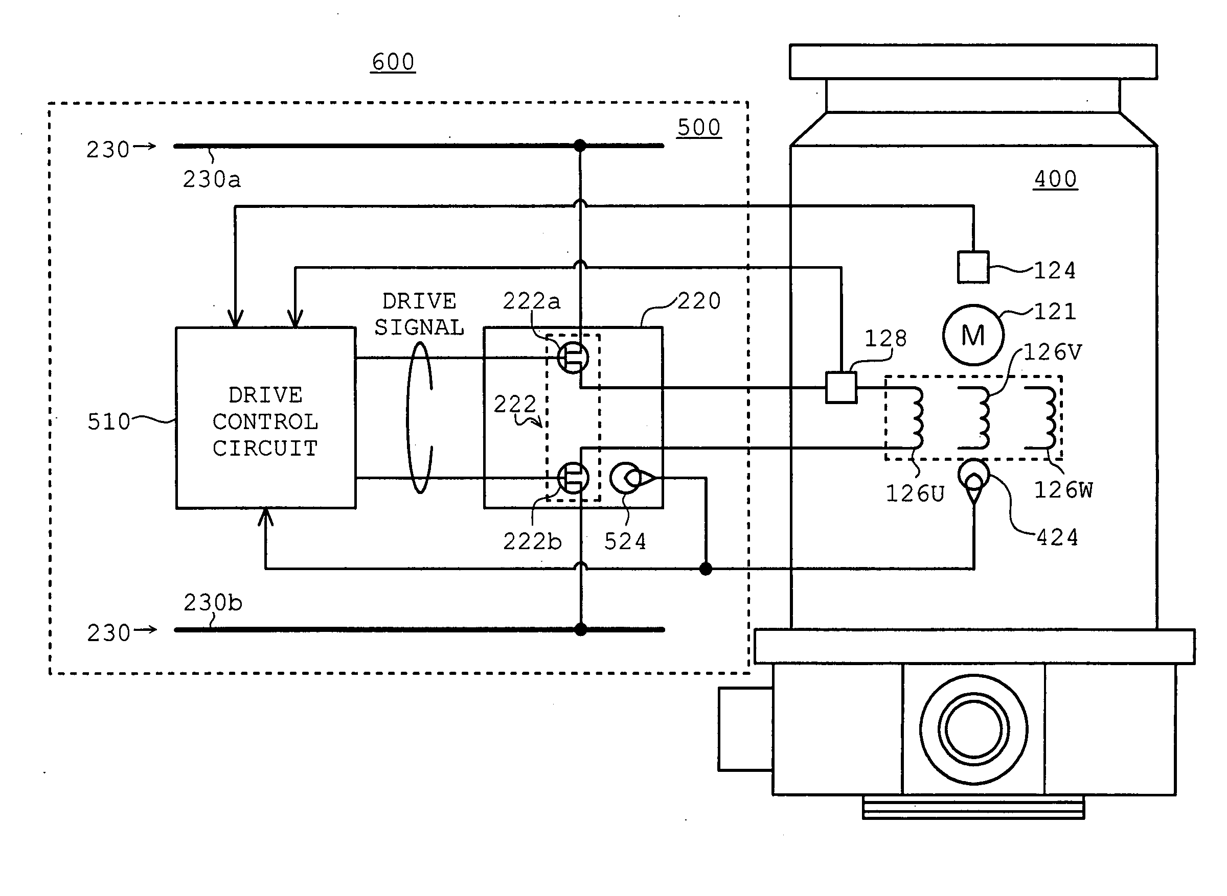
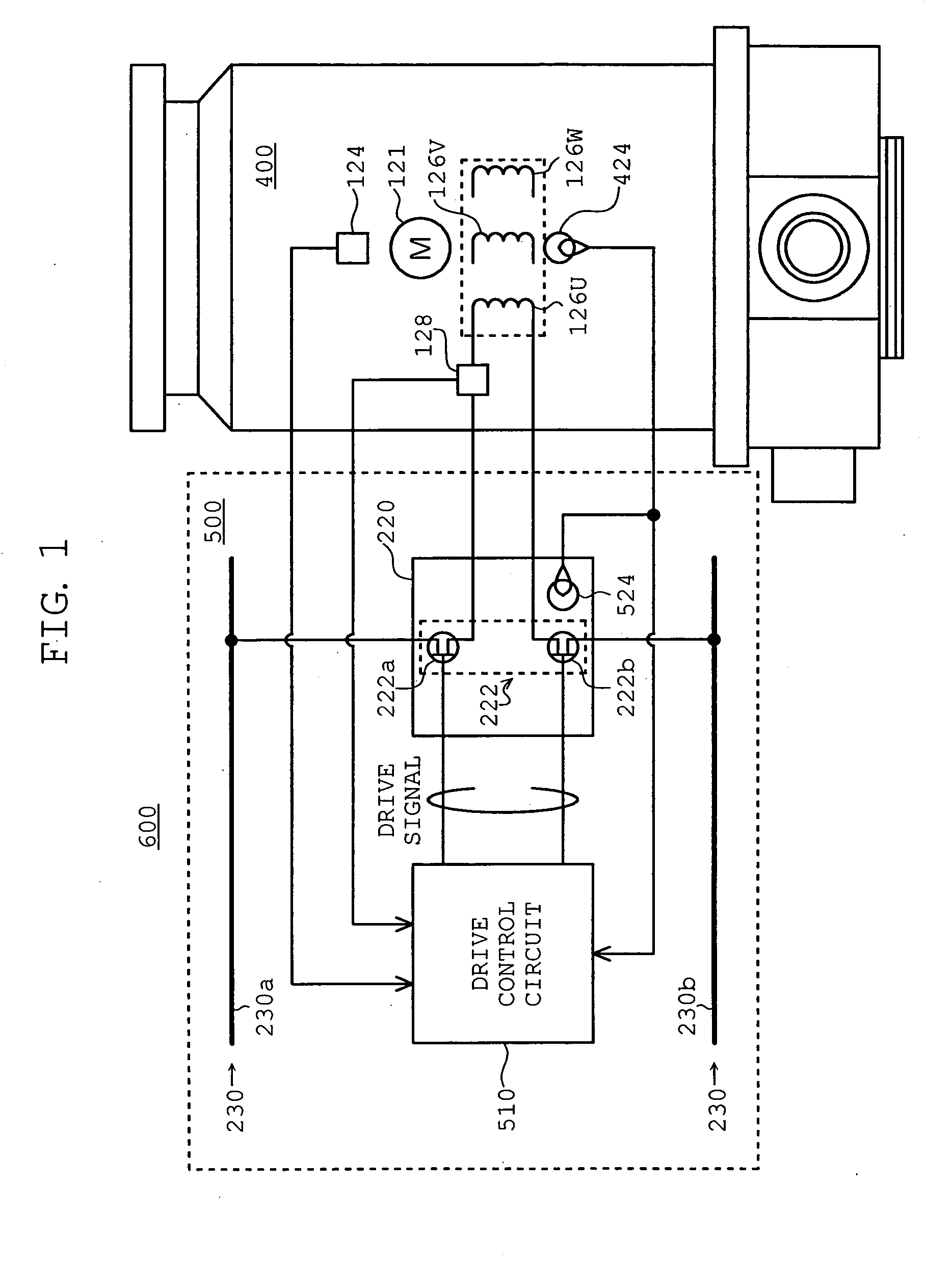
[0099]FIG. 1 shows the configuration of a motor control system according to an embodiment of the present invention. The components that are the same as those of FIG. 8 are indicated by the same symbols, and a description thereof will be omitted.

[0100] In FIG. 1, a motor control system 600 includes a turbo molecular pump main body 400, in which motor windings 126U, 126V, and 126W are equipped with a motor temperature sensor 424. The motor temperature sensor 424 consists, for example, of a thermistor, which is adapted to detect the temperature of the motor windings 126U, 126V, and 126W.

[0101] Further, the motor control system includes a control device 500, in which also the inverter circuits 222 are equipped with an inverter temperature sensor 524. The inverter temperature sensor 524 also consists, for example, of a thermistor, which is adapted to detect the temperature of transistors 222a, 222b, etc. constituting ea...


PUM


Abstract

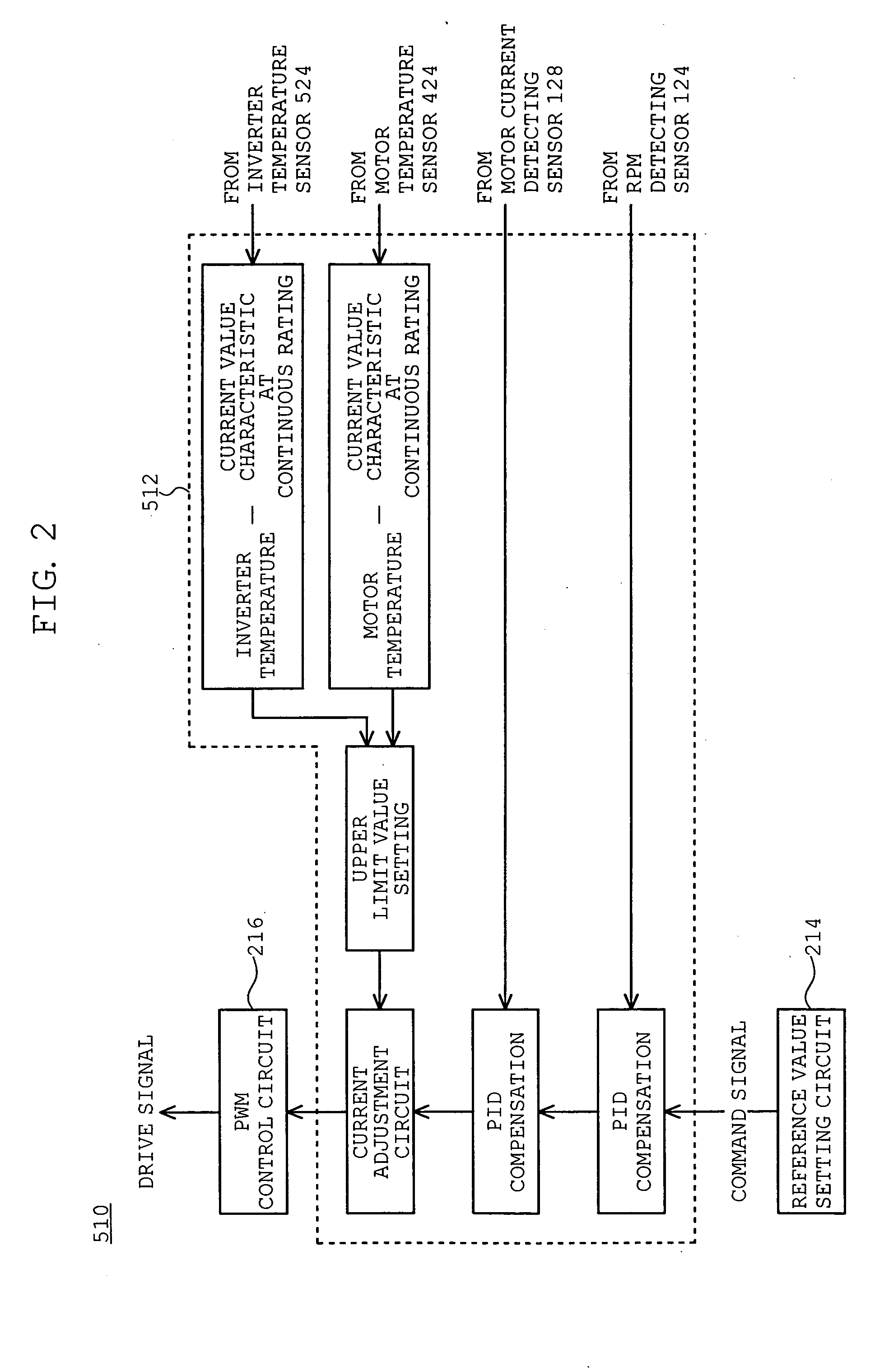
Disclosed are a motor control system capable of shortening the starting time of a turbo molecular pump and a vacuum pump equipped with the motor control system. A motor control system (600) is equipped with a motor temperature sensor (424) and an inverter temperature sensor (524). Detection signals from the motor temperature sensor (424) and the inverter temperature sensor (524) are input to a comparator (512) of a drive control circuit (510). In accordance with a characteristic curve and based on the temperatures detected by the motor temperature sensor (424) and the inverter temperature sensor (524), the comparator (512) sets, in a current adjustment circuit, a current value at continuous rating satisfying both motor windings (126U, 126V, and 126W) and inverter circuits (222) as the upper limit value of a motor current Im.

Description

BACKGROUND OF THE INVENTION [0001] 1. Field of the Invention [0002] The present invention relates to a motor control system and a vacuum pump equipped with the motor control system, and more particularly to a motor control system capable of shortening the starting time of a turbo molecular pump and a vacuum pump equipped with the motor control system. [0003] 2. Description of the Related Art [0004] As a result of recent developments in electronics, there is a rapidly increasing demand for semiconductor devices, such as memories and integrated circuits. [0005] Such semiconductor devices are manufactured by doping semiconductor substrates of a very high purity with impurities to impart electrical properties thereto, by stacking together semiconductor substrates with minute circuit patterns formed thereon, etc. [0006] In order to avoid the influences of dust in the air, etc., such operations must be conducted in a chamber in a high vacuum state. To evacuate the chamber, a vacuum pump i...

Claims


Application Information

Patent Timeline
Patent Type & Authority Applications(United States)
IPC IPC(8): F04D27/00F04D19/04H02P1/00H02P1/28H02P6/06H02P6/08H02P6/28
CPCH02P1/28F04D19/04F04D27/0261F05D2260/85Y02B30/70
Inventor SOMEYA, OSAMU
Owner EDWARDS JAPAN
Learn More